Acquisition Procedure in a PLC |
Top Previous Next |
|
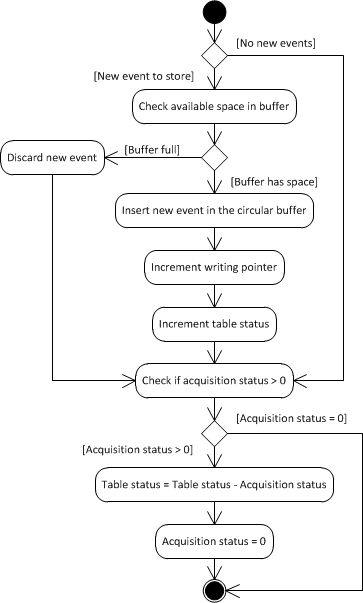
This topic presents a discussion about an algorithm for collecting events from the point of view of a PLC or slave device. Its goal is to clarify to developers what must be implemented in PLC's resident application (ladder). A device must start inserting events in ascending order, starting at table's base address, that is, starting at the circular buffer. For each new event inserted, the Recording Pointer must be incremented, pointing to the next available position in that buffer. This Driver performs a reading starting from the oldest to the newest event. The starting address of this reading is calculated by this Driver using the value of Recording Pointer and Table Status. If the number of available events is greater than protocol's maximum allowed into a single communication frame, this Driver performs multiple block readings, updating the value of Acquisition Status after finishing this process with the total amount of events read.
When detecting a non-null value written by this Driver to Acquisition Status, a PLC's or device's application must immediately subtract Acquisition Status' value from Table Status' value and then zeroes Acquisition Status. With Acquisition Status zeroed again, this Driver can start a new acquisition at any time. A PLC can insert new events to a table during PLC's acquisition process, as long as there is no overflow on circular buffer, that is, as long as its writing pointer does not exceed its reading pointer, by incrementing Table Status. An event collecting or downloading procedure is finished when Table Status is zeroed. All collected events are then provided to an application via event-reported Tags, as described on the next topic. The next figure shows a flow chart, as a UML Activity Diagram, with a suggestion of implementation for a PLC logic. Notice that some variations are possible, for example discarding the oldest event in case of overflow, which can be evaluated by a developer, depending on the context.  UML Activity Diagram (PLC) TimestampAs already mentioned, every event is composed by a structure containing one or more data elements (usually, but not necessarily, represented by User-Defined Data Types). If structures (user-defined data types) are used, then users can associate a timestamp to each PLC-provided event. In this case, the value of the Timestamp field must be provided in a structure field, in PLC memory, in the order it was declared in the configuration file, and its value is not displayed in any Block Element, it is only returned in the Timestamp property of the linked Tag. As explained on topic User-Defined Data Types, any date and time type supported by this Driver can be used. The GenTime data type, however, was specially created for use with Elipse Modbus SOE, due to an easy definition in PLC's resident application (ladder). If a millisecond precision is needed, another option is consider Driver's UTC32 data type, represented as an integer with only 32 bits (4 bytes) with seconds starting at 1/1/1970, without a milliseconds representation, considered as 0 (zero). The next topic, Acquisition Procedure in an Application, describes how to configure an application for collecting events accumulated in a PLC or programmable slave device. |