Perspective and Nonlinear Distortion Calibration
Perspective errors and lens aberrations cause images to appear distorted. This distortion misplaces information in an image, but it does not necessarily destroy the information in the image. Calibrate your imaging system if you need to compensate for perspective errors or nonlinear lens distortion.
Complete the following general steps to calibrate your imaging system:
- Define a calibration template.
- Define a reference coordinate system.
- Learn the calibration information.
After you calibrate your imaging system, you can attach the calibration information to an image. Refer to the Attach Calibration Information section for more information. Then, depending on your needs, you can perform one of the following steps:
- Use the real-world measurements options on the IMAQ Particle Analysis and IMAQ Particle Analysis Report VIs to get real-world particle shape parameters without correcting the image.
- Use the calibration information to convert pixel coordinates to real-world coordinates without correcting the image.
- Create a distortion-free image by correcting the image for perspective errors and lens aberrations.
Defining a Calibration Template
You can define a calibration template by supplying an image of a grid or providing a list of pixel coordinates and their corresponding real-world coordinates. This section discusses the grid method of defining a calibration template in detail.
A calibration template is a user-defined grid of circular dots. As shown in the following figure, the grid has constant spacings in the x- and y-directions. You can use any grid, but follow these guidelines for best results:
- The displacement in the x- and y-directions should be equal (dx = dy).
- The dots should cover the entire required working area.
- The radius of the dots in the acquired image should be 6 to 10 pixels.
- The center-to-center distance between dots in the acquired image should range from 18 to 32 pixels, as shown in the following figure.
- The minimum distance between the edges of the dots in the acquired image should be six pixels, as shown in the following figure.
 |
|
| 1 Center-to-Center Distance | 3 Distance Between Dot Edges |
| 2 Center of Grid Dots | |
 |
Note Select Start»All Programs»National Instruments»Vision»Documentation»Calibration Grid to use the calibration grid installed with NI Vision. The dots have radii of 2 mm and center-to-center distances of 1 cm. Depending on your printer, these measurements may change by a fraction of a millimeter. You can purchase highly accurate calibration grids from optics suppliers, such as Edmund Industrial Optics. |
Defining a Reference Coordinate System
To express measurements in real-world units, you need to define a coordinate system in the image of the grid. Use the Calibration Axis Info control of the IMAQ Set Simple Calibration VI to define a coordinate system by its origin, angle, and axis direction.
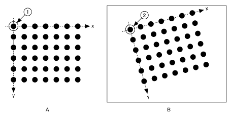
The origin, expressed in pixels, defines the center of your coordinate system. The angle specifies the orientation of your coordinate system with respect to the angle of the topmost row of dots in the grid image. The calibration procedure automatically determines the direction of the horizontal axis in the real world. The vertical axis direction can either be indirect, as shown in Figure A, or direct, as shown in Figure B.

If you do not specify a coordinate system, the calibration process defines a default coordinate system. If you specify a grid for the calibration process, the software defines the following default coordinate system, as shown in the following figure:
- The origin is placed at the center of the leftmost, topmost dot in the calibration grid.
- The angle is set to 0×. This aligns the x-axis with the first row of dots in the grid, as shown in Figure A.
- The axis direction is set to Indirect. This aligns the y-axis to the first column of the dots in the grid, as shown in Figure B.
 |
|
| 1 Origin of a Calibration Grid in the Real World | 2 Origin of the Same Calibration Grid in an Image |
If you specify a list of points instead of a grid for the calibration process, the software defines a default coordinate system, as follows:
- The origin is placed at the point in the list with the lowest x-coordinate value and then the lowest y-coordinate value.
- The angle is set to 0°.
- The axis direction is set to Indirect.
If you define a coordinate system yourself, carefully consider the needs of your application.
- Express the origin in pixels. Always choose an origin location that lies within the calibration grid so that you can convert the location to real-world units.
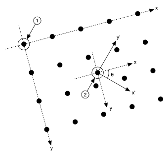
- Specify the angle as the angle between the x-axis of the new coordinate system (x') and the top row of dots (x), as shown in the following figure. If your imaging system exhibits nonlinear distortion, you cannot visualize the angle as you can in the following figure because the dots do not appear in straight lines.
 |
|
| 1 Default Origin in a Calibration Grid Image | 2 User-Defined Origin |
Learning Calibration Information
After you define a calibration grid and reference axis, acquire an image of the grid using the current imaging setup. Refer to the Acquire or Read an Image section for information about acquiring images. The grid does not need to occupy the entire image. You can choose a region within the image that contains the grid. After you acquire an image of the grid, learn the calibration information by inputting the image of the grid and the real-world distances between the dots into the IMAQ Learn Calibration Template VI.
 |
Note If you want to specify a list of points instead of a grid, use the Reference Points control of the IMAQ Learn Calibration Template VI to specify the pixel to real-world mapping. |
Specifying Scaling Factors
Scaling factors are the real-world distances between the dots in the calibration grid in the x- and y- directions and the units in which the distances are measured. Use the X Step and Y Step elements of the Grid Descriptor control to specify the scaling factors.
Choosing a Region of Interest
Define a learning ROI during the learning process to define a region of the calibration grid you want to learn. The software ignores dot centers outside this region when it estimates the transformation. Depending on the calibration options selected, this is an effective way to increase correction speeds. Set the learning ROI using the Calibration Learn Setup control of the IMAQ Learn Calibration Template VI.
 |
Note The user-defined learning ROI represents the area in which you are interested. Do not confuse the learning ROI with the calibration ROI generated by the calibration algorithm. |
Choosing a Learning Algorithm
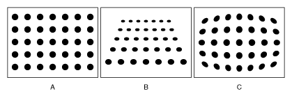
Select a method in which to learn the calibration information: perspective projection or nonlinear. The following figure illustrates the types of errors your image can exhibit. Figure A shows an image of a calibration grid with no errors. Figure B shows an image of a calibration grid with perspective projection. Figure C shows an image of a calibration grid with nonlinear distortion.

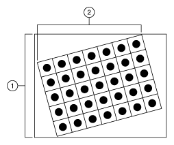
Choose the perspective projection algorithm when your system exhibits perspective errors only. A perspective projection calibration has an accurate transformation even in areas not covered by the calibration grid, as shown in the following figure. Set the Distortion element of the Calibration Learn Setup control to Perspective to choose the perspective calibration algorithm. Learning and applying perspective projection is less computationally intensive than the nonlinear method. However, perspective projection is not designed to handle highly nonlinear distortions.
If your imaging setup exhibits nonlinear distortion, use the nonlinear method. The nonlinear method guarantees accurate results only in the area that the calibration grid covers, as shown in the following figure. If your system exhibits both perspective and nonlinear distortion, use the nonlinear method to correct for both. Set the Distortion element of the Calibration Learn Setup control to Nonlinear to choose the nonlinear calibration algorithm.
 |
|
| 1 Calibration ROI Using the Perspective Algorithm | 2 Calibration ROI Using the Nonlinear Algorithm |
Using the Learning Score
The learning process returns a score that reflects how well the software learned the input image. A learning score above 800 indicates that you chose the appropriate learning algorithm, that the grid image complies with the guideline, and that your vision system setup is adequate.
If the learning process returns a learning score below 600, try the following:
- Make sure your grid complies with the guidelines listed in the Defining a Calibration Template section.
- Check the lighting conditions. If you have too much or too little lighting, the software may estimate the center of the dots incorrectly. Also, adjust the Threshold Range to distinguish the dots from the background.
- Select another learning algorithm. When nonlinear lens distortion is present, using perspective projection sometimes results in a low learning score.
 |
Note A high score does not reflect the accuracy of your system. |
Learning the Error Map
An error map helps you gauge the quality of your complete system. The error map returns an estimated error range to expect when a pixel coordinate is transformed into a real-world coordinate. The transformation accuracy may be higher than the value the error range indicates. Set the Learn Error Map? element of the Calibration Learn Setup control to learn the error map.
Learning the Correction Table
If the speed of image correction is a critical factor for your application, use a correction table. A correction table is a lookup table, stored in memory, that contains the real-world location information of all the pixels in the image. The extra memory requirements for this option are based on the size of the image. Use this option when you want to correct several images at a time in your vision application. Set the Learn Correction Table? element of the Calibration Learn Setup control to learn the correction table.
Setting the Scaling Method
Use the Corrected Image Scaling element of the Calibration Learn Setup control to choose the appearance of the corrected image. Select either Scale to Fit or Scale to Preserve Area.Refer to Chapter 3, System Setup and Calibration, of the NI Vision Concepts Manual for more information about the scaling mode.
Calibration Invalidation
Any image processing operation that changes the image size or orientation voids the calibration information in a calibrated image. Examples of VIs that void calibration information include the IMAQ Resample, IMAQ Extract, IMAQ ArrayToImage, and IMAQ Unwrap VIs.