Locate Objects to Inspect
In a typical machine vision application, you extract measurements from ROIs rather than the entire image. To use this technique, the parts of the object you are interested in must always appear inside the ROIs you define.
If the object under inspection is always at the same location and orientation in the images you need to process, defining ROIs is straightforward. Refer to the section of this chapter for information about selecting an ROI.
Often, the object under inspection appears shifted or rotated in the image you need to process, relative to the reference image in which you located the object. When this occurs, the ROIs need to shift and rotate with the parts of the object in which you are interested. For the ROIs to move with the object, you need to define a reference coordinate system relative to the object in the reference image. During the measurement process, the coordinate system moves with the object when the object appears shifted and rotated in the image you need to process. This coordinate system is referred to as the measurement coordinate system. The measurement VIs automatically move the ROIs to the correct position using the position of the measurement coordinate system relative to the reference coordinate system. Refer to Chapter 14, Dimensional Measurements, of the NI Vision Concepts Manual for information about coordinate systems.
You can build a coordinate transformation using edge detection or pattern matching. The output of the edge detection and pattern matching VIs that build a coordinate transformation are the origin, angle, and axes direction of the coordinate system. Some machine vision VIs take this output and adjust the regions of inspection automatically. You also can use these outputs to move the regions of inspection relative to the object programmatically.
Using Edge Detection to Build a Coordinate Transformation
You can build a coordinate transformation using two edge detection techniques. Use the IMAQ Find CoordSys (Rect) 2 VI to define a reference coordinate system using one rectangular region. Use the IMAQ Find CoordSys (2 Rects) 2 VI to define a reference coordinate system using two independent rectangular regions. Complete the following steps to build a coordinate transformation using edge detection.
- Specify one or two rectangular regions.
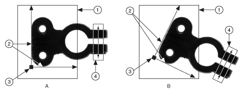
- If you use the IMAQ Find CoordSys (Rect) 2 VI, specify one rectangular ROI that includes part of two straight,
nonparallel boundaries of the object, as shown in the following figure. This rectangular region must be large enough
to include these boundaries in all the images you want to inspect.

1 Search Area for the Coordinate System 3 Origin of the Coordinate System 2 Object Edges 4 Measurement Area - If you use the IMAQ Find CoordSys (2 Rects) 2 VI, specify two rectangular ROIs, each containing one separate,
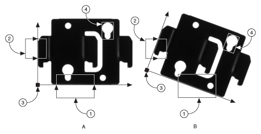
straight boundary of the object, as shown in the following figure. The boundaries cannot be parallel. The regions
must be large enough to include the boundaries in all the images you want to inspect.

1 Primary Search Area 3 Origin of the Coordinate System 2 Secondary Search Area 4 Measurement Area
- If you use the IMAQ Find CoordSys (Rect) 2 VI, specify one rectangular ROI that includes part of two straight,
nonparallel boundaries of the object, as shown in the following figure. This rectangular region must be large enough
to include these boundaries in all the images you want to inspect.
- Choose the parameters you need to locate the edges on the object.
- Choose the coordinate system axis direction.
- Choose the results that you want to overlay onto the image.
- Choose the mode for the VI. To build a coordinate transformation for the first time, set mode to Find Reference. To update the coordinate transformation in subsequent images, set this mode to Update CoordSys.
Using Pattern Matching to Build a Coordinate Transformation
You can build a coordinate transformation using pattern matching. Use the IMAQ Find CoordSys (Pattern) 2 VI to define a reference coordinate system based on the location of a reference feature. Use this technique when the object under inspection does not have straight, distinct edges. Complete the following steps to build a coordinate transformation using pattern matching:
 |
Note The object can rotate 360° in the image using this technique if you use rotation-invariant pattern matching. |
- Define a template that represents the part of the object that you want to use as a reference feature.
- Define a rectangular search area in which you expect to find the template.
- Choose the Match Mode. Select Rotation Invariant when you expect your template to appear rotated in the inspection images. Otherwise, select Shift Invariant.
- Choose the results that you want to overlay onto the image.
- Choose the mode for the VI. To build a coordinate transformation for the first time, set mode to Find Reference. To update the coordinate transformation in subsequent images, set this mode to Update CoordSys.
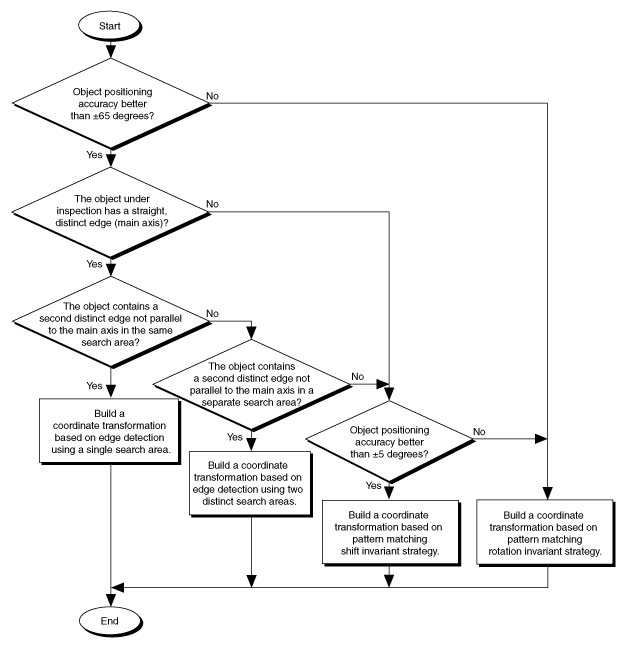
Choosing a Method to Build the Coordinate Transformation
The flowchart in the following figure guides you through choosing the best method for building a coordinate transformation for your application.
