ni5660 Configure Reference Clock
From NI PXI-5660
ni5660 Configure Reference Clock
Use this function to configure the reference clock source for the RF Signal Analyzer. Reference clock source options include the high-stability oven-controlled crystal oscillator (OCXO) onboard the RF downconverter module (On Board Clock), a 10 MHz reference clock from an external source (Ref In), or the PXI backplane (PXI Clock 10). You can optionally use this VI to drive the PXI backplane using the specified reference clock source.
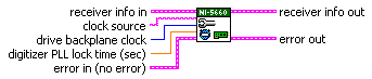
| receiver info in is the instrument handle that you obtain from the ni5660 Initialize VI. The handle identifies a particular RF Signal Analyzer session. |
clock source specifies the RF Signal Analyzer reference clock source. Select one of the following options:
|
| drive backplane clock specifies whether the reference clock specified in the clock source parameter is propagated to the PXI backplane. When drive backplane clock is FALSE (default), the PXI backplane is independent of the RF Signal Analyzer timebase. When drive backplane clock is TRUE, the PXI backplane is driven by the specified RF Signal Analyzer clock source. Default Value: FALSE |
| Note This option is only available when the RF downconverter module is installed in PXI Slot 2, and the PXI 10 MHz I/O connector is wired to the 10 MHz OUT connector on the NI 5600 RF downconverter module front panel as shown in Overview. |
| digitizer PLL lock time (sec) specifies time in seconds for which the digitizer module reference clock must be phase-locked to the 10 MHz reference of the downconverter module before execution. For most measurements, the PLL may be considered stable after 1 second, but NI recommends a digitizer PLL lock time of 4 seconds to ensure complete settling and utmost accuracy for phase measurements. Default Value: 1.0 second
|
| error in accepts error information wired from previously called VIs.
The pop-up option Explain Error (or Explain Warning) gives more information about the error displayed.
|
receiver info out passes a reference to your instrument session to the next VI.
receiver info was obtained from the ni5660 Initialize VI.
|
error out passes error or warning information out of a VI to be used by other VIs. The pop-up option Explain Error (or Explain Warning) gives more information about the error displayed.
|