ni5660 Configure for IQ
From NI PXI-5660
ni5660 Configure for IQ
This VI configures the RF Signal Analyzer hardware to acquire a time-domain signal with IQ settings you specify. Carrier frequency, bandwidth, and acquisition time settings define the IQ data. You can configure the acquisition to be finite or continuous.
This VI configures the reference level and attenuation settings used by the RF downconverter module, and the horizontal settings and acquisition type used by the IF digitizer module.
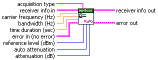
| acquisition type specifies whether the acquisition is finite or continuous. Default Value: FINITE |
| receiver info in is the instrument handle that you obtain from the ni5660 Initialize VI. The handle identifies a particular RF Signal Analyzer session. |
| carrier frequency (Hz) specifies the expected carrier frequency of the incoming signal for demodulation. The RF Signal Analyzer tunes to this frequency. This value may be coerced based on hardware settings and downconversion specifications. Default Value: 100 MHz |
| bandwidth (Hz) specifies the 0.01 dB down filter bandwidth of the software filter that is used in the downconversion process. Set this value equal to the bandwidth in Hz of the modulated wave. This value may be coerced based on hardware settings and downconversion specifications. Default Value: 1 MHz |
| time duration (sec) specifies the time duration/interval in seconds over which to acquire IQ data. This control is ignored if acquisition type is set to CONTINUOUS. Default Value: 10 µseconds |
| error in accepts error information wired from previously called VIs.
The pop-up option Explain Error (or Explain Warning) gives more information about the error displayed.
|
| reference level (dBm) specifies the expected total integrated power of the RF input signal in dBm. Refer to Signal Levels for more information. Default Value: 0 dBm. |
| auto attenuation specifies whether the attenuation setting is automatically determined or user-specified. Set this parameter to DISABLE to specify a downconverter module attenuation setting using the attenuation parameter. When auto attenuation is set to ENABLE (default), NI-RFSA automatically chooses an attenuation setting that optimizes noise and distortion levels for the specified reference level. When this parameter is set to ENABLE, the attenuation parameter is ignored. Default Value: ENABLE |
attenuation (dB) specifies the downconverter module attenuation setting in dB. This VI uses the reference level and attenuation parameters to calculate the desired signal level at the first input mixer. Mixer level values influence noise and distortion factors as follows:
Calculate the attenuation setting using desired reference level and mixer level settings, according to the formula: For example, when using a reference level of 0 dBm (default) with moderate distortion and low noise, specify an attenuation value of 20 dB:
Default Value: 20 dB |
receiver info out passes a reference to your instrument session to the next VI.
receiver info was obtained from the ni5660 Initialize VI.
|
error out passes error or warning information out of a VI to be used by other VIs. The pop-up option Explain Error (or Explain Warning) gives more information about the error displayed.
|