MT Phase Locked Loop VI
Attempts to track the unknown phase of an input complex exponential tone by means of a feedback control system. At steady state, when the phase-locked loop (PLL) has acquired a lock to the input signal, the PLL estimates the offset of the input signal carrier phase and carrier frequency from the reference phase and frequency. The polymorphic instances of this VI accept either a complex baseband waveform or a real passband waveform.
Use the pull-down menu to select an instance of this VI.
MT Baseband PLL
This polymorphic instance simulates the operation of the PLL in response to an input complex baseband waveform with an unknown phase and frequency offset.
The baseband waveform is assumed to consist of a tone at a user-specified nominal carrier phase and frequency, which is used as a reference to the PLL. The PLL is a feedback control system that employs a phase detector, loop filter, and a voltage-controlled oscillator (VCO) for its operation. The PLL tracks the instantaneous phase and frequency of the input waveform and returns an estimate of the carrier phase and frequency. You can use these estimates to adjust/correct the phase of the input waveform (for example, carrier phase/frequency offset correction in M-ary PSK digital communication systems).

 |
baseband waveform specifies a cluster comprising the I/Q baseband waveform values that represent the complex envelope. The complex envelope is assumed to consist of a tone with a frequency and phase that are to be estimated by the PLL. The default is empty.
|
||||||
 |
VCO gain specifies the gain applied to the error signal inside the VCO prior to generating the estimated initial phase parameter. The default is 1. |
||||||
 |
VCO carrier frequency specifies the reference carrier frequency used by the VCO to track the carrier phase of the input signal. The default is 0 Hz. |
||||||
 |
VCO initial phase specifies the reference initial carrier phase used by the VCO to track the carrier phase of the input signal. The default is 0 degrees. |
||||||
 |
loop filter (forward coefficients) specifies the forward coefficients of the IIR loop filter. The default is (1.05 -0.95) |
||||||
 |
loop filter (reverse coefficients) specifies the reverse coefficients of the IIR loop filter. The default is (1 -1). |
||||||
 |
reset ? specifies whether to clear the internal state of the PLL prior to starting operation.
|
||||||
 |
error in (no error) accepts error information wired from previously called VIs. Use this information to decide if any functionality should be bypassed in the event of errors from other VIs. Right-click the front panel error in control and select Explain Error or Explain Warning from the shortcut menu for more information about the error displayed.
|
||||||
 |
VCO phase returns the overall phase of the input signal estimated by the PLL, including the effects of any carrier phase and frequency offsets. |
||||||
 |
phase error returns the carrier phase error signal at the phase detector output inside the PLL. You can use this value to estimate the phase difference between the input signal and the regenerated phase at the PLL output. When the PLL locks, phase error values approach zero. |
||||||
 |
estimated carrier frequency returns the actual carrier frequency of the input signal, as estimated by the PLL, accounting for any carrier frequency offset. Use the difference between the estimated carrier frequency and the nominal input carrier frequency to estimate the carrier frequency offset. |
||||||
 |
estimated initial phase returns the actual carrier phase of the input signal, as estimated by the PLL, with respect to the specified nominal carrier phase. Use the difference between the estimated carrier phase and the input nominal carrier phase to estimate the scalar carrier phase offset. |
||||||
 |
error out passes error or warning information out of a VI to be used by other VIs. Right-click the front panel error out indicator and select Explain Error or Explain Warning from the shortcut menu for more information about the error displayed.
|
MT Passband PLL
This polymorphic instance simulates the operation of the phase-locked loop (PLL) in response to an input real passband waveform that has an unknown phase and frequency offset.
The passband waveform is assumed to consist of a tone at a user-specified nominal carrier phase and frequency, which is used as a reference to the passband PLL. The PLL is a feedback control system that employs a phase detector, loop filter, and a voltage-controlled oscillator (VCO) for its operation. The passband PLL tracks the instantaneous phase and frequency of the input waveform and returns an estimate of the carrier phase and frequency. You can use these estimates to adjust/correct the phase of the input waveform (for example, carrier phase/frequency offset correction in M-ary PSK digital communication systems).

 |
passband waveform specifies a passband waveform comprising a tone at the carrier, with a frequency and phase that are to be tracked by the PLL. |
||||||
 |
VCO carrier frequency specifies the reference carrier frequency used by the VCO to track the carrier phase of the input signal. The default is 0 Hz. |
||||||
 |
VCO initial phase specifies the reference initial carrier phase used by the VCO to track the carrier phase of the input signal. The default is 0 degrees. |
||||||
 |
VCO gain specifies the gain applied to the error signal inside the VCO prior to generating the estimated initial phase parameter. The default is 1. |
||||||
 |
loop filter (reverse coefficients) specifies the reverse coefficients of the IIR loop filter. The default is (1 -1). |
||||||
 |
loop filter (forward coefficients) specifies the forward coefficients of the IIR loop filter. The default is (1.05 -0.95) |
||||||
 |
reset ? specifies whether to clear the internal state of the PLL prior to starting operation.
|
||||||
 |
error in (no error) accepts error information wired from previously called VIs. Use this information to decide if any functionality should be bypassed in the event of errors from other VIs. Right-click the front panel error in control and select Explain Error or Explain Warning from the shortcut menu for more information about the error displayed.
|
||||||
 |
VCO phase returns the overall phase of the input signal estimated by the PLL, including the effects of any carrier phase and frequency offsets. |
||||||
 |
phase error returns the carrier phase error signal at the phase detector output inside the PLL. You can use this value to estimate the phase difference between the input signal and the regenerated phase at the PLL output. When the PLL locks, phase error values approach zero. |
||||||
 |
estimated carrier frequency returns the actual carrier frequency of the input signal, as estimated by the PLL, accounting for any carrier frequency offset. Use the difference between the estimated carrier frequency and the nominal input carrier frequency to estimate the carrier frequency offset. |
||||||
 |
estimated initial phase returns the actual carrier phase of the input signal, as estimated by the PLL, with respect to the specified nominal carrier phase. Use the difference between the estimated carrier phase and the input nominal carrier phase to estimate the scalar carrier phase offset. |
||||||
 |
error out passes error or warning information out of a VI to be used by other VIs. Right-click the front panel error out indicator and select Explain Error or Explain Warning from the shortcut menu for more information about the error displayed.
|
Details
You must set the following parameters to configure the PLL operation:
- loop filter (reverse coefficients)—The reverse coefficients of the IIR loop filter.
- loop filter (forward coefficients)—The forward coefficients of the IIR loop filter.
- VCO gain—The gain that is applied to the error signal inside the VCO prior to generating the estimated phase output.
- VCO carrier frequency—The reference carrier frequency used by the VCO to track the carrier phase of the input signal.
- VCO initial phase—The reference initial carrier phase used by the VCO to track the carrier phase of the input signal.
 |
Note The PLL VIs are continuable, meaning that you can successively send a phase-continuous signal to the VI over multiple iterations when reset? is set to FALSE. The PLL VI performs the following measurements on the input baseband waveform:
|

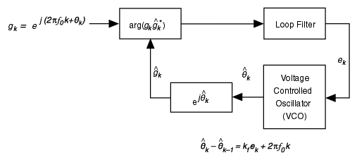
A PLL contains three basic elements:
- Phase detector
- IIR loop filter
- Voltage controlled oscillator (VCO)
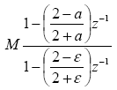
The phase detector block measures the approximate error between the estimated phase and the actual phase of the incoming signal. The IIR loop filter block then filters out any high-frequency noise present in the error signal and helps tracking phase and frequency offset errors. A first-order lowpass filter block tracks an initial phase offset, but returns a constant phase offset in the presence of a frequency offset. Higher-order filters track both phase and frequency offsets at steady state, as summarized in the following table.
| F(s) | F(z) | Remarks |
|---|---|---|
| 1 | 1 | (Order I) Tracks frequency error, steady state phase offset |

|

|
(Order II) Tracks phase and frequency error, not offset |

|

|
(Order II) Tracks phase and frequency error, not offset |

|

|
(Order III) Tracks phase and frequency error, not offset |


