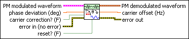
MT Demodulate PM VI

LabView Analog Modulation

MT Demodulate PM VI

Performs phase demodulation on the incoming I/Q signal. The information signal is computed as a result of the demodulation and returned in the PM demodulated waveform output. This VI calculates any offset from the expected carrier frequency specified in the MT Configure Downconversion Settings VI.

Details

MT Demodulate PM

ccclst.gif

PM modulated waveform specifies the baseband (downconverted) time-domain data for demodulation.

cdbl.gif

t0 specifies the trigger (start) time of the acquired signal.

cdbl.gif

dt specifies the time interval between data points in the acquired signal.

c1dcdb.gif

Y specifies the complex-valued time-domain data array. The real and imaginary parts of this complex data array correspond to the in-phase (I) and quadrature-phase (Q) data, respectively.

cdbl.gif

phase deviation specifies how to scale the PM demodulated waveform. You can set this value to 1.0 or to the expected phase deviation of the incoming PM signal for demodulation.

  • Set this value equal to 1.0 to return a PM demodulated waveform in degrees with no scaling. In this case, the maximum amplitude of the PM demodulated waveform is equal to the actual phase deviation of the incoming PM signal. If the information signal is a single tone, you can use the Extract Single Tone Information VI to measure the maximum amplitude of the PM demodulated waveform.
  • Set this value equal to the expected phase deviation of the incoming PM signal to divide the PM demodulated waveform by this value. You can use the resulting scaled PM demodulated waveform to quantify the degree of error between the expected phase deviation and the actual phase deviation.
cbool.gif

carrier correction? toggles carrier correction? on and off.

TRUE

When carrier correction? is TRUE, the VI determines a linear correction to the carrier frequency estimate and compensates for it in the PM demodulated waveform.

FALSE Set carrier correction? to FALSE when performing continuous acquisition. This is the default value.
cbool.gif

reset? controls initialization of an internal VI state that tracks the ending phase.

TRUE

Set reset? to TRUE to clear the state information about each call.

FALSE

When reset? is set to FALSE, the final phase from the previous call serves as the starting phase for the next call, ensuring phase continuity between calls. This is the default value.

ccclst.gif

error in (no error) accepts error information wired from previously called VIs. Use this information to decide if any functionality should be bypassed in the event of errors from other VIs. Right-click the front panel error in control and select Explain Error or Explain Warning from the shortcut menu for more information about the error displayed.

cbool.gif

status is either TRUE (X) for an error, or FALSE (checkmark) for no error or a warning. Right-click the front panel error in control and select Explain Error or Explain Warning from the shortcut menu for more information about the error displayed.

ci32.gif

code identifies the error or warning. Right-click the front panel error in control and select Explain Error or Explain Warning from the shortcut menu for more information about the error displayed.

cstr.gif

source describes the origin of the error or warning. Right-click the front panel error in control and select Explain Error or Explain Warning from the shortcut menu for more information about the error displayed.

iwfm.gif

PM demodulated waveform returns the phase-demodulated information signal.

idbl.gif

carrier offset returns the offset between the incoming modulated carrier frequency and the estimated carrier frequency passed to the MT Configure Downconversion Settings VI. Offset is returned whether carrier correction? is TRUE or FALSE. If the carrier frequency drifts as a function of time, this VI calculates the offset by performing a weighted linear fit on the phase information in the I/Q signal, and then taking the slope of this linear fit. You can use this slope to monitor drift in the carrier frequency.

icclst.gif

error out passes error or warning information out of a VI to be used by other VIs. Right-click the front panel error out indicator and select Explain Error or Explain Warning from the shortcut menu for more information about the error displayed.

ibool.gif

status is either TRUE (X) for an error, or FALSE (checkmark) for no error or a warning. Right-click the front panel error in control and select Explain Error or Explain Warning from the shortcut menu for more information about the error displayed.

ii32.gif

code identifies the error or warning. Right-click the front panel error in control and select Explain Error or Explain Warning from the shortcut menu for more information about the error displayed.

istr.gif

source describes the origin of the error or warning. Right-click the front panel error in control and select Explain Error or Explain Warning from the shortcut menu for more information about the error displayed.

Details

If the actual carrier frequency of the acquired signal is different from the center frequency of the receiver, a slope and offset are introduced into the PM demodulated waveform parameter. If the carrier correction? parameter is set to TRUE, this slope and offset are removed. This correction is made only in software; the VI does not attempt to establish a lock with the unit under test (UUT).

You can wire the PM demodulated waveform parameter to any of the LabVIEW waveform measurement VIs for further measurements.