Multiple Directive Example 1
Directives highlighted in this example are:
radix#includeequorgendProgram Functional Description
This program continually alternates the output on the Port B pins from 1's to 0's. Two delay routines using interrupts provide the timing for the alternating output. If LEDs were attached to Port B, they would flash (1=on, 0=off).
The type of PICmicro MCU is set using
processor, and the radix is set to hexadecimal usingradix. The standard header file for the processor selected is included using#include. Registers are assigned using theequdirective. Sections of code are blocked out using theorgstatement. Finally, the program is finished with anend.Commented Code Listing
;**************************************
;* MPASM Assembler Control Directives *
;* Example Program 1 *
;* Alternate output on Port B between *
;* 1's and 0's *
;**************************************
processor 16f877 ;Set the processor
radix hex ;Set the radix
#include <p16f877.inc> ;Include header file
DTEMP equ 0x20 ;Set temp register
DFLAG equ 0x21 ;Set flag register
DFL0 equ 0x00 ;Set flag bit
org 0x00 ;Reset Vector
goto Start
org 0x04 ;Interrupt Vector
goto ServInt
org 0x06 ;Start Program
Start
clrf PORTB ;Clear PortB
bsf STATUS, RP0 ;Select Bank 1
clrf TRISB ;Set PortB as output
bcf STATUS, RP0 ;Select Bank 0
bsf INTCON, GIE ;Enable Global Int's
bsf INTCON, T0IE ;Enable Timer0 Int
Loop
movlw 0xFF
movwf PORTB ;Set PortB
call Delay1 ;Wait
clrf PORTB ;Clear PortB
bsf PCLATH,3 ;Select Page 3
bsf PCLATH,4
call Delay2 ;Wait
bcf PCLATH,3 ;Select Page 0
bcf PCLATH,4
goto Loop ;Repeat
ServInt ;Interrupt Serice Routine
bsf STATUS, RP0 ;Select Bank 1
bsf OPTION_REG, T0CS ;Stop Timer0
bcf STATUS, RP0 ;Select Bank 0
bcf INTCON, T0IF ;Clear overflow flag
bcf DFLAG, DFL0 ;Clear flag bit
retfie
;***************************************
;* Delay 1 Routine - Timer0 delay loop *
;***************************************
Delay1
movlw 0xF0 ;Set Timer0 value
movwf TMR0 ;0x00-longest delay
;0xFF-shortest delay
clrf DFLAG
bsf DFLAG, DFL0 ;Set flag bit
bsf STATUS, RP0 ;Select Bank 1
bcf OPTION_REG, T0CS ;Start Timer0
bcf STATUS, RP0 ;Select Bank 0
TLoop
btfsc DFLAG, DFL0 ;Wait for overflow
goto TLoop ;Timer0 0xFF->0x00
return
;******************************************
;* Delay 2 Routine - Decrement delay loop *
;******************************************
org 0x1900 ;Page 3
Delay2
movlw 0xFF ;Set DTEMP value
movwf DTEMP ;0x00-shortest delay
;0xFF-longest delay
DLoop
decfsz DTEMP, F
goto DLoop ;End loop when DTEMP=0
return
end
Additional Comments
Header Files
A header file is included in the program flow with the
#includedirective.#include <p16f877.inc> ;Include header file
Angle brackets are used to enclose the name of the file to be included, although quotes may also be used. You may specify the complete path to the included file, or let the assembler search for it. For more on search order, see the discussion of the
#includedirective ().A header file is extremely useful for specifying often-used constants, such as register and pin names. This information can be typed in once, and then the file can be included in any code using the processor with those registers and pins.
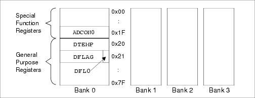
Register and Bit Assignments
You can specify your own registers and bits by using the
equdirective, as is done in the following lines.DTEMP equ 0x20 ;Set temp register
DFLAG equ 0x21 ;Set flag register
DFL0 equ 0x00 ;Set flag bit
DTEMPandDFLAGare assigned to the values0x20and0x21respectively. They will be used in delay loops in the program to stand for the general purpose registers (GPRs) 0x20 and 0x21.DFL0is assigned the value0x00and will be used as the name for pin 0 in theDFLAGregister.Figure: PIC16F877 Register File Map
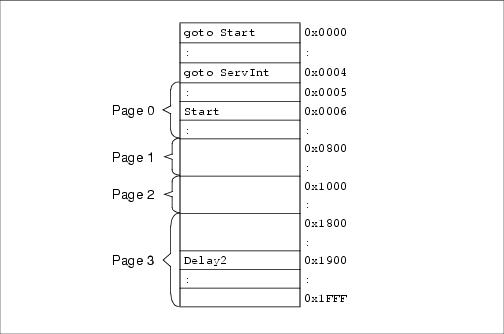
Using ORG
The
orgdirective is used to specify the program origin for specific sections of code. If noorgis used, code generation begins at address zero. For Example 1,orgis used to specify code at 0x00 (reset address), 0x04 (interrupt address), 0x06 (program start address) and 0x1900 (Delay2 address).Figure: PIC16F877 Program Memory Map
Most of the program is contained on page 0. However, the code for delay routine
Delay2has been placed on page 3. When calling this routine, you must remember to use the paging bits in thePCLATHto select page 3, and then use them to switch back to page 0 on the return.bsf PCLATH,3 ;Select Page 3
bsf PCLATH,4
call Delay2 ;Wait
bcf PCLATH,3 ;Select Page 0
bcf PCLATH,4
|
Microchip Technology Inc. Microchip's Web Site Voice: (480) 792-7200 Fax: (480) 899-9210 Microchip's E-mail Address |
 
|