Simple Example
From MiWi Development Environment
The simple example application code focuses on the simplicity of the MiWi™ DE protocol stack application programming interfaces. It provides a clean and straightforward wireless communication between two devices with less than 30 lines of effective C code to run the stack in application layer for both devices. In this application, following features of MiWi™ DE protocol stack have been demonstrated:
• Establish connection automatically between two devices
• Broadcast a packet
• Unicast a packet
• Apply security to the transmitted packet
Following two diagrams show the MiApp flow chart of two nodes respectively.
Simple Node 1 Flow Chart

Simple Node 2 Flow Chart

To run the simple example application, following is the instruction:
- Program node 1 and node 2 with proper firmware. We assume that the users are familiar with Microchip tool chain and have no problem compile and program the firmware to the demo boards.
- Power on node 1 and node 2 respectively
- Wait a few seconds, until the first LED (RA0 on PICDEM Z, D8 on PIC18 Explorer or D10 on Explorer 16) on both nodes light up. These are the steps to establish connections between two devices.
- This means a connection has been established automatically. For the details of connection establishment, please refer to section “VARIATIONS FOR HANDSHAKING” in application note AN1204 “Microchip MiWi™ P2P Wireless Protocol" if MiWi™ P2P protocol is used, or section "MAC Function Description" in IEEE 802.15.4 specification if MiWi™ protocol is used.
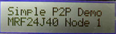
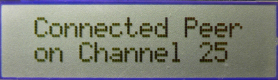
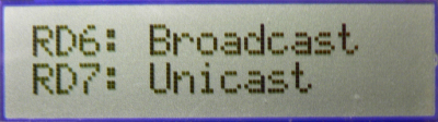
- If the demo is running on PIC18 Explorer, 8-bit wireless demo board or Explorer 16 demo boards, critical information will be shown on the LCD of the demo board. It first shows the demo name, RF transceiver and node number, then connecting information and channel information will be shown before the LCD shows the demo instruction: button 1 for broadcast and button 2 for unicast.
 |
 |
 |
|
|
 |
- If MRF24J40 transceiver is demonstrated and ZENA network analyzer is used, the default channel is 25. You should be able to see the hand-shaking procedure with exchanged packets between two nodes.

- If a hyper terminal has been opened to monitor firmware output, you should be able to see the information about the peer device printed out from both nodes.

- Press button 1 (RB5 on PICDEM Z, RB0 on PIC18 Explorer or RD6 on Explorer 16) on one node will toggle the second LED (RA1 on PICDEM Z, D7 on PIC18 Explorer or D9 on Explorer 16) on the other node
- This shows how a broadcast packet has been transmitted.
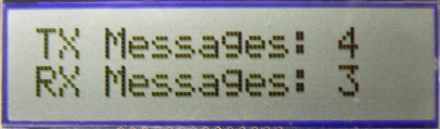
- If the demo is running on PIC18 Explorer or Explorer 16 demo board, the total number of transmitted and received messages will be shown on the LCD.
 |
- If ZENA network analyzer is used, you should be able to see that a broadcast packet with various bytes has been sent out.
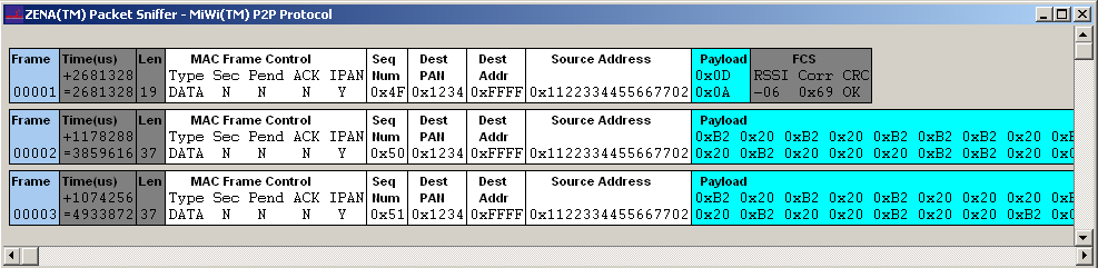
- If hyper terminal has been used, on the receiving end (the device that has LED2 toggled), you should be able to see the print out of broadcast packet source address, signal strength and the packet payload. The packet payload is the one line of bit map of “HELLO”. Press the button 1 continuously on one end will display the complete bit map of "HELLO".

- Press button 2 (RB4 on PICDEM Z, RA5 on PIC18 Explorer or RD7 on Explorer 16) on one node will toggle the second LED (RA1 on PICDEM Z, D7 on PIC18 Explorer or D9 on Explorer 16) on the other node.
- This shows how an encrypted unicast packet has been transmitted and decrypted by the radio after it is received. For the details of how MiWi™ P2P handles encryption, please refer to section “Security Features” in application note AN1204 “Microchip MiWi™ P2P Wireless Protocol”.
- If the demo is running on PIC18 Explorer or Explorer 16 demo board, the total number of transmitted and received messages will be shown on the LCD.
|
|
- If ZENA network analyzer is used, you should be able to see that a unicast packet with various bytes has been transmitted from one device and the acknowledgement packet with 5 bytes transmitted from the other device. You will also notice that the unicast packet is encrypted.

- By pressing the button with a key icon on the MiWi™ Network Monitor window, the encrypted packet can be decrypted with correct security setting. For the security setting, the key is 0x0F0E0D0C0B0A09080706050403020100 and the security level is AES-CCM-32. Press the button of “Accept Security Parameters” will apply the security setting to decrypt the packets. If your ZENA software disables the security feature, you need to order a full version ZENA through Microchip agent to be compliant with US export control regulation.

- If hyper terminal has been used, on the receiving end (the device that has LED2 toggled), you should be able to see the print out of secured unicast packet source address, signal strength and the packet payload. The packet payload should have been decrypted by the receiving device. The packet payload is the one line of bit map of “P2P”. Press the button 2 continuously on one end will display the complete bit map of "P2P".
