PIC18 Explorer
From MiWi Development Environment
1) Set the S4 switch on PIC18 Explorer at the position of ICE.

2) Before connecting the PIM to the PIC18 Explorer board, remove all attached cables. Connect the PIM to the PIC18 Explorer board. Be careful when connecting the boards to insure that no pins are bent or damaged during the process. Also ensure that the PIM is not shifted in any direction and that all of the headers are properly aligned.
3) Connect the either the MRF24J40, MRF49XA or MRF89XA RF board to the PICTail connector. Be aware that the transceiver chip should face the PIM and the first pin should be plugged into the hole labeled "RE2".
The configured hardware setup for PIC18 Explorer board should look like following picture.

PIC18 Explorer support both RS232 serial port and USB to connect to the PC for monitoring. PIC18 Explorer by default is configured to use the RS232 serial port to communicate with PC. Following steps setup the PIC18 Explorer to use USB port.
1. Hardware Setup
Configure the Explorer PIC18 demo board to use USB connection by setting jumper J13 according to the following diagram

Make sure toggle switch is in the DOWN – ICE position. This switch activates the PIC18 on the PIM. DO NOT remove the PIM or the board Vdd will be 5V, which may damage the RF module.
2. USB Driver Install
- Connect the PIC18 Explorer demo board to the PC using a USB cable.
- Power up PIC18 Explorer demo board, following pop up window will appear

- Select "Install from a list or specific location" option and click "Next". Following pop up window appear

- Select the check box "Include this location in the search", in the text box, browse to "<Install Directory>\PC Software" folder. This is the location of the "mchpcdc.inf" driver.
- Click "Next". There may be warning from Windows operating system about installing a driver without digital signature. Please ignore that warning and continue. After the driver is installed properly, the following screen will appear

- Click "Finish". USB port is ready to be used.
3. Open Hyper Terminal
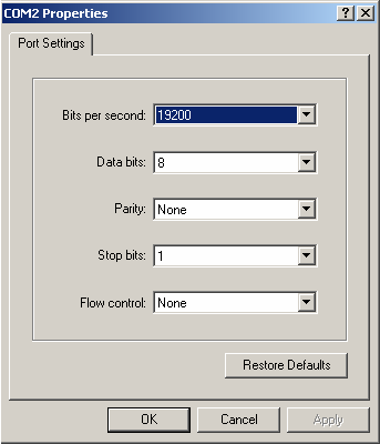
Once the RS232 serial or USB cable is connected between the demo board and PC, launch a hyper terminal to display the information from the demo board. The hyper terminal configuration is baud rate 19200, Data bit 8, Parity None, Stop bits 1 and Flow control None, as shown below.
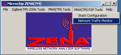
In the case that Microchip MRF24J40 transceiver is used in the demo, ZENA™ network analyzer can be used to monitor the network traffic of IEEE 802.15.4 network. To run ZENA™ sniffer, connect the ZENA board with PC through the USB interface, then launch ZENA software. The ZENA window will show up. Choose “MiWi™ P2P Tools” Menu or "MiWi(TM) Tools" Menu, depending on the protocol is used, and then click the menu item “Network Traffic Monitor” to launch Network Monitor window.
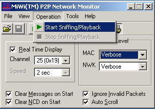
From the Network Monitor window, check “Real Time Display” box and choose proper channel. By default, this demo use channel 25. Choose “Operation” menu and click “Start Sniffing/Playback” menu item to launch the “ZENA™ Packet Sniffer” window to monitor the wireless traffic.
In the case Microchip MRF49XA or MRF89XA transceiver is used in the demo, setting the RF utility driver in the receiving mode can be used as the basic sniffer, though packet decoding is not supported.