The feature demo application code demonstrates the rich features of MiWi™ DE protocol stack. It shows how the stack manages to operate on optimal condition as well as robustness of the stack that can recover from operating environment change. In this application, in addition to features shown in simple example application, following features of MiWi™ DE protocol stack have been demonstrated:
- Network Freezer feature that restores network after power cycle.
- Active Scan to locate existing PAN in the neighborhood
- Energy Scan to find channel with least noise
- Sleeping device to conserve energy to be able to be powered by battery
- Indirect message to be able to deliver message to sleeping device
- Frequency agility capability that is able to change operating channel in case operating environment changes
- Resynchronization capability that is able to resynchronize with the original PAN in case operating channel was changed
Following two diagrams show the MiApp flow chart of two nodes respectively.
Feature Demo Node 1 Flow Chart

Feature Demo Node 2 Flow Chart

To run the feature demo application, following is the instruction:
- Program the proper firmware to node 1 and node 2 respectively. We assume that the users are familiar with Microchip tool chain and have no problem to compile and program the firmware to the demo boards.
- Power on Node 1
If this device has been part of network before and you would like to restore the previous network configuration, follow steps below to restore network configuration in node 1.
- Press and hold button 1 on node 1 before powering on
- Power on node 1 for 5 seconds.
- Release button 1 on node 1. At this time, the network has been recovered and you could get to step 4 to power on node 2; otherwise, continue on step 3 to start the network.
- Wait a while until the LED1 lights up on node 1.
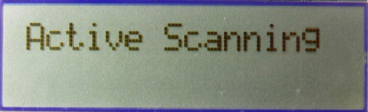
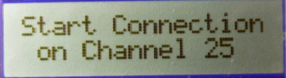
- In this step, an active scan and a possible energy scan has been done by node 1. The PAN has been established on the channel with least noise. For details of active scan and energy scan, please refer to sections “Active Scan” and “Energy Scan” in Microchip application note AN1204 “Microchip MiWi™ P2P Wireless Protocol” if MiWi™ P2P is used as the protocol, or section "MAC Function Description" in IEEE 802.15.4 specification if MiWi™ protocol is used.
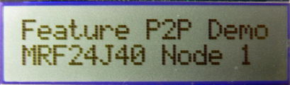
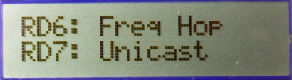
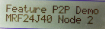
- If PIC18 Explorer, 8-bit Wireless demo board or Explorer 16 demo boards are used in the demo, the demo name, RF transceiver and node number will be displayed on the LCD first. Then the message of active scan and energy scan will be displayed respectively. Finally, the demo instruction will be displayed on the LCD: button 1 for frequency hopping and button 2 for indirect unicast to sleeping device.
 |
 |
 |
|
|
 |
|
|
 |
|
|
 |
- If MRF24J40 is demonstarted and ZENA network analyzer is used, no matter what channel you are monitoring, you should be able to see a broadcast command. That is the active scan from node 1. After the LED1 lights up, if hyper terminal is used to monitor firmware output, please change the ZENA monitor channel to where the PAN has established, based on the print out on the hyper terminal.

- If hyper terminal has been connected between PC and demo board, you should see from the hyper terminal that node 1 does an active scan first. If there is any MiWi™ P2P or MiWi™ PAN established in the neighborhood, you should be able to see the printout of the list of available PANs. If one of the PANs has the same PAN identifier as the desired one, node 1 will try to establish a connection with that PAN. Otherwise, node 1 will do an energy scan. You should be able to see the energy reading on each channel printed out on the hyper terminal. At the end, you will see that node 1 establishes the PAN on the channel with least noise, or energy reading.

- Power on node 2
If this device has been part of network before and you would like to restore the previous network configuration, follow steps below to restore network configuration in node 2.
- Press and hold button 1 on node 2 before powering on
- Power on node 2 for 5 seconds.
- Release button 1 on node 2. At this time, the network has been recovered and you could get to step 6 to perform transmission and receiving; otherwise, continue on step 5 to join the network.
- Wait a few seconds until the LED1 lights up on node 2.
- In this step, an active scan has been done by node 2; node 1 has responded to node 2’s active scan and node 2 established a P2P connection with node 1. For details of active scan, please refer to section “Active Scan” in Microchip application note AN1204 “Microchip MiWi™ P2P Wireless Protocol” if MiWi™ P2P protocol is used, or section "MAC Function Description" in IEEE 802.15.4 specification if MiWi™ protocol is used.
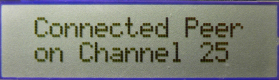
- If PIC18 Explorer, 8-bit Wireless demo board or Explorer 16 demo board is used in the demo, critical information will be displayed on the LCD of the demo board. The demo name, RF transceiver and node number will be displayed first, followed by the information of active scan during the process. Once the active scan is finished and the device has been connected to the peer, the connected information and the channel number will be displayed for a short time before the demo instruction being displayed: button 1 for broadcast. For Explorer 16 demo board, button 2 can also be used to wake up the device and send encrypted unicast message.
 |
|
|
|
|
|
|
 |
- If MRF24J40 transceiver is demonstrated and ZENA network analyzer is used and the monitor channel is the operating channel of the PAN, you should be able to see a broadcast packet. That is an active scan from node 2. Then node 1 responds to the active scan by unicast a packet to node 2. You will then see the 5-byte acknowledgement from node 1 to node 2. A few seconds later, a broadcast packet from node 2 initiates the hand-shaking process with node 1. You will see that node 1 responds with a unicast message to node 2 and node 2 acknowledge the unicast packet from node 1. After the hand-shaking procedure is done, a connection has been established. You will then see that node 2 sends out a Data Request command to node 1 about every 8 seconds to retrieve possible message from node 1 to node 2. Node 1 will acknowledge the Data Request command and later unicast an empty packet, if there is no message to node 2.

- If RS232 serial port or USB cable has been connected, you should see from the hyper terminal that node 2 does an active scan first and then prints out all operating MiWi™ P2P or MiWi™ PAN on the screen. Later, node 2 will choose the PAN that matches its own PAN identifier and starts the hand-shaking procedure. After the hand-shaking procedure has been completed, the LED1 lights up and the information about its peer device, node 1, will be printed out on the hyper terminal.

- Press button 1 or button 2 on node 2 will wake up node 2 immediately from sleeping mode and send a broadcast or encrypted unicast message, just as the way that has been demonstrated in the simple example application. Because of demo board hardware design, for PIC18 Explorer demo board, only button 1 is able to wake up the the node 2 device and send out data. Pressing button 2 on PIC18 Explorer demo board will not be able to wake up the node 2 and sending out data.
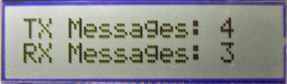
- If PIC18 Explorer, 8-bit Wireless demo board or Explorer 16 demo boards are used, the total number of transmitted and received messages will be displayed on the LCD of the demo board.
 |
- Press button 2 on node 1 will send a secured unicast message to node 2.
- Since node 2 is a RFD device that sleeps during idle, the message will not be delivered immediately. This kind of message is defined as indirect message. When node 2 wakes up next time within about 8 seconds, the indirect message will be delivered after the node 2 sends out Data Request command. After node 2 receives the indirect message, it will toggle its LED2. For details of indirect message, please refer to sections “Idle Devices Turning Off Radios” in Microchip application note AN1204 “Microchip MiWi™ P2P Wireless Protocol” if MiWi™ P2P protocol is used, or section "MAC Function Description" in IEEE 802.15.4 specification if MiWi™ protocol is used.
- If PIC18 Explorer, 8-bit Wireless demo board or Explorer 16 demo board is used in the demo, the delivery of indirect message to the sleeping device will be displayed on the LCD on both demo boards. Be aware that due to the delay in delivery indirect message, there is also a delay between the sender update number of the transmitted messages and receiver update the number of received messages.
|
|
- If MRF24J40 transceiver is demonstrated and ZENA network analyzer is used, you should be able to see that the message is delivered to node 2 followed by a Data Request command.

- If RS232 serial port or USB cable has been connected on node 2, you should able to see the printout of the received packet, as we have discussed in simple example application.

- Press button 1 (RB5 on PICDEM Z, RB0 on PIC18 Explorer or RD6 on Explorer 16) on node 1 will initiate the frequency agility feature of MiWi™ P2P or MiWi™ stack. For details of frequency agility, please refer to sections “Frequency Agility” in Microchip application note AN1204 “Microchip MiWi™ P2P Wireless Protocol” if MiWi™ P2P protocol is used.
- In this step, node 1 will start the frequency agility procedure. In this demo, node 1 is the frequency agility starter and node 2 is the frequency agility follower. Node 1 will first do an energy scan on all channels other than the current operating one to ensure a channel hopping. Then node 1 will choose the channel with least noise as the next operating channel for the PAN and broadcast the channel hopping command with the next operating channel to all devices that can hear. For those devices that do not hear the channel hopping command, such as a RFD like node 2 with its radio off during idle, a resynchronization procedure will start to re-establish the connection after transmission failures occur predefined times,.
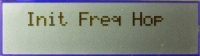
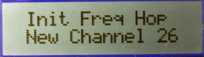
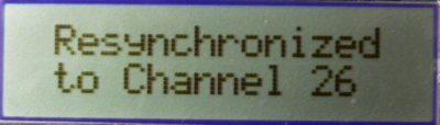
- If PIC18 Explorer, 8-bit Wireless demo board or Explorer 16 demo board is used in the demo, node 1 will display the frequency hopping process and the new channel that node 1 has hopped to. Node 2, on the other hand, will display the increasing number of losing connection with peer until it starts to re-synchronize the connection and its hop to the new channel of the peer.
|
Frequency Hopping Initiator |
Frequency Hopping Follower |
 |
 |
|
|
|
 |
 |
|
|
|
|
|
 |
- If MRF24J40 transceiver is demonstrated and ZENA network analyzer is used, you should be able to see that the Data Request command from node 2 fails after button 1 of node 1 is pressed. Later, you will later see a broadcast channel hopping command from node 1.

- On the new operating channel, a resynchronization command will be sent from node 2. Node 1 will respond to the resynchronization command. After that, you can see normal Data Request procedure going on at the new operating channel.

- If RS232 serial port or USB has been connected on node 1, you should able to see the energy reading on each channel. Finally, node 1 will change to the channel with lowest energy reading.

- If RS232 serial port or USB has been connected on node 2, you should be able to see the printout of Data Request failure for three times. After the failure for the fourth time, the resynchronization procedure will start and finally the node 2 will be resynchronized to the channel that node 1 chose before.
