Drawing the Rows

Adding Tiles to the Garden Path

Looking at the Code

Now that you have the logic for drawing the path, the next step is to figure out how to draw the tiles in each row. In the following diagram, there are two cases shown: a row where the offset from the center of the path is equal to 0.0, and a case where the offset is not equal to zero. Take a look at the diagram, then read the pseudo-code that follows.
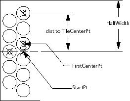
Set up variables for StartPoint, angp90, angm90, and so on.
Set the variable FirstCenterPoint to the StartPoint + offset amount
(which may be 0.0).
Set the initial value of TileCenterPt to FirstCenterPoint.
(Comment: Begin by drawing the circles in the angp90 direction.)
While the distance from the StartPoint to the TileCenterPt is less than the HalfWidth:
Draw a circle (adding to the accumulating list of circles).
Set TileCenterPt to the next tile space increment in the angp90
direction.
End While
Reset the TileCenterPoint to the FirstCenterPoint + the tile space increment at angm90.
While the distance from the StartPoint to the TileCenterPt is less than the HalfWidth:
Draw a circle (adding to the accumulating list of circles).
Set TileCenterPt to the next tile space increment in the angm90
direction.
End While
Return the list of circles.