flex_load_commutation_parameter |
Load Commutation Parameter
Usage
i32 status = flex_load_commutation_parameter (u8 boardID, u8 axis, u16 attribute, f64 value);
Purpose
Sets a commutation parameter for a given axis.
Parameters
| Name | Type | Description |
|---|---|---|
| boardID | u8 | assigned by Measurement & Automation Explorer (MAX) |
| axis | u8 | axis to configure |
| attribute | u16 | attribute to configure |
| value | f64 | value to load for the specified attribute |
Parameter Discussion
axis is the axis to configure. Valid values are NIMC_AXIS1 through NIMC_AXIS30. On motion controllers that support fewer than thirty axes, configuring non-existent axes returns error 70006 (NIMC_badResourceIDOrAxisError). Refer to Axes for axis resource IDs.
attribute is one of the following commutation attributes to set:
| Constant | Value | Description |
| NIMC_COMM_INITIALIZATION_TYPE | 0 | Loads the Initialization Type for sinusoidal commutation. |
| NIMC_COMM_FIND_ZERO_VOLT | 1 | Loads Find Zero Voltage for sinusoidal commutation. |
| NIMC_COMM_FIND_ZERO_TIME | 2 | Loads Find Zero Time for sinusoidal commutation. |
| NIMC_COMM_DIRECT_SET_PHASE | 3 | Loads Direct Set Phase for sinusoidal commutation. |
| NIMC_COMM_ELECTRICAL_CYCLE_COUNTS | 4 | Loads the Electrical Cycle Counts for sinusoidal commutation. |
| NIMC_HALL_SENSOR_TYPE | 5 | Loads the Hall Effect Sensor type for sinusoidal commutation. |
| NIMC_COMM_MODE | 6 | Loads the Commutation Mode for sinusoidal commutation. |
value is dependent upon the specified commutation attribute. Select the appropriate value for the corresponding attribute:
| Attribute | Value | Description |
| NIMC_COMM_INITIALIZATION_TYPE (0) | 0 NIMC_HALL_SENSOR 1 NIMC_SHAKE_AND_WAKE 2 NIMC_DIRECT_SET |
Set the value to Hall Sensor, Shake and Wake, or Direct Set for the Initialization Type. |
| NIMC_COMM_FIND_ZERO_VOLT (1) | 0 to 10 volts | Set the value in volts for Find Zero Volt. |
| NIMC_COMM_FIND_ZERO_TIME (2) | 0 to 10,000 ms | Set the value in milliseconds for Find Zero Time. |
| NIMC_COMM_DIRECT_SET_PHASE (3) | 0 to 359° | Set the value in degrees for Direct Set Phase. |
| NIMC_COMM_ELECTRICAL_CYCLE_COUNTS (4) | 2 to 268,534,000 counts | Set the value in counts for Electrical Cycle Counts. |
| NIMC_HALL_SENSOR_TYPE (5) | 0 NIMC_HALL_SENSOR_TYPE_1 1 NIMC_HALL_SENSOR_TYPE_2 |
Set the value to Type 1 or Type 2 for the Hall Sensor Type. |
| NIMC_COMM_MODE (6) | 0 NIMC_EXTERNAL_COMMUTATION 1 NIMC_ONBOARD_COMMUTATION |
Set the value to External Commutation or Onboard Commutation for the Communication Mode. |
Using This Function
Use the Load Commutation Parameter function to configure a commutation parameter for a given axis.
 |
Note Only 7350 controllers support the Load Commutation Parameter function. |
Initialization Type specifies how the controller initializes the commutation phase. Select one of the following values:
| Value | Description |
| 0 | Hall Sensor—Initializes the phase based on the Hall sensor's input. |
| 1 | Shake and Wake—Initializes the phase by driving the system to the zero degree commutation phase. |
| 2 | Direct Set—Sets the commutation phase directly with the phase angle specified. |
 |
Caution Phase initialization is performed when the axes are enabled. If you use Shake and Wake, the system can move during the initialization process. |
Find Zero Voltage specifies the voltage to use with Shake and Wake initialization. The range is 0 to 10 volts. Find Zero Time specifies the duration of Shake and Wake initialization in milliseconds. The range is 0 to 10,000 ms.
Direct Set Phase specifies phase angle to set with Direct Set initialization. For Direct Set, the controller sets the current position as the specified phase angle. National Instruments recommends this initialization method only for custom systems with a known initial phase angle. The range for the phase angle is 0 to 359°.
Electrical Cycle Counts specifies the encoder counts for the commutation cycle. This information is usually listed in the motor or stage documentation. Some motor manufacturers present this information as the number of poles. In such cases, convert number of poles to counts per electrical cycle with the following equation. The valid data range is 2 to 268,435,000 counts.

 |
Caution Counts per electrical cycle must be set correctly to avoid overheating and damaging the motor. |
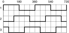
Hall Sensor Type specifies the type of Hall Effect sensor to use. There are two base types of Hall Effect sensor inputs. If you are using Type 1, the pattern matches the following graph:

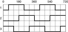
If you are using Type 2, the pattern matches the following graph:

Refer to your motor documentation for information about the type of Hall Effect sensor to use. Refer to the documentation for your 7350 device for information about configuring Hall Effect sensors. Select one of the following values:
| Value | Description |
| 0 | Type 1 |
| 1 | Type 2 |
Commutation Mode configures the axis to use onboard commutation or to be commutated externally. Select one of the following values:
| Value | Description |
| 0 | External Commutation |
| 1 | Onboard Commutation |
Call the Load Commutation Parameter function before enabling the axis. If the axis is enabled, the commutation parameters does not take effect until you call Enable Axis again.