7. Estimating a Model
From NI MAX System Identification Assistant
7. Estimating a Model
You can use the LabVIEW System Identification Assistant to estimate the parameters of a model for an unknown system. Models enable you to predict the response of a system given only the stimulus.
In the previous exercises, you processed data to make calculations during model estimation and model validation easier. You now can use the processed data to estimate a model for the motor. A model of the motor can estimate the motor speed given a stimulus voltage. The more accurate the model is, the closer the estimated motor speed is to the actual response of the system.
Complete the following steps to estimate the parameters of an ARX model for the motor.
- From the LabVIEW SignalExpress menu bar, select Add Step»System Identification»Model Estimation»Parametric Estimation to add a Parametric Estimation step to the Project View.
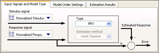
- On the Input Signals and Model Type tab in the Configuration View, select Normalized Stimulus from the Stimulus signal pull-down menu to specify Normalized Stimulus as the input stimulus signal to use to estimate the model.

Note If the System Identification Assistant displays an error message stating The signal length is too small for computation, or the stimulus and response signals are not of the same length., you can ignore this error. This error message displays because the Stimulus signal and Response signal, which you specify in the next step, have different lengths. - Select Normalized Response from the Response signal pull-down menu to specify Normalized Response as the input response signal to use to estimate the model.
- Verify that ARX is the model type in the Type pull-down menu. This pull-down menu specifies the model type whose parameters you want to estimate by using the selected input signals. The Input Signals and Model Type tab contains a diagram of the model you want to build, as shown in the figure below.
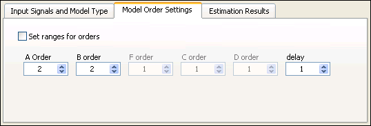
- On the Model Order Settings tab, set both A Order and B order to 2 to set up a second-order model. Setting A Order to 2 configures the System Identification Assistant to determine the value of the response signal based on the two previous values of that signal. Setting B order to 2 configures the System Identification Assistant to determine the value of the stimulus signal based on the two previous values of that signal.
- Verify that 1 is the delay in the delay option. A delay of 1 applies a delay of one sample time to the stimulus signal. The following figure shows the correct configuration of the Model Order Settings tab.
- Notice the two graphs in the Configuration View. Both graphs illustrate the accuracy of the model estimation. The Response Signals graph displays the original response to the Normalized Stimulus signal and the estimated response of the configured ARX model to the Normalized Stimulus signal. Recall that Normalized Response is the original response to Normalized Stimulus. The more the two signals in the Response Signals graph overlap, the more accurate the model estimation is. In this example, the signals overlap very closely, which means the estimated model is a close approximation to the system.
Similarly, the Simulation Error graph displays the difference between the two signals shown in the Response Signals graph. The closer the values of the Simulation Error graph are to 0, the more accurate the model estimation is. In this example, the Simulation Error is very close to 0, which means the estimated model is a close approximation to the system. Notice, however, that the value of Simulation Error asymptotically goes to 0. The model uses data from previous sample times to compute its estimated response. Therefore, at the initial stage of the response, the model does not have sufficient previous data for estimation, and the Simulation Error is significantly large. - On the Estimation Results tab, notice that the small values of the FPE, AIC, and MDL also illustrate the accuracy of the model estimation. When these values are close to 0, the estimated model is a close approximation of the system.
- In the Project View, rename the SysID Model output to ARX Model.
- Select File»Save Project to save the project.
| Previous: 6. Normalizing Validation Data | Next: 8. Viewing Model Information |