Setting Up and Configuring Your System
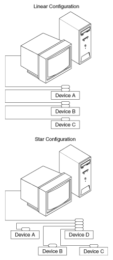
Devices are usually connected with a cable assembly consisting of a shielded 24-conductor cable with both a plug and receptacle connector at each end. With this design, you can link devices in a linear configuration, a star configuration, or a combination of the two. The following picture shows the linear and star configurations.

Controlling More Than One Board
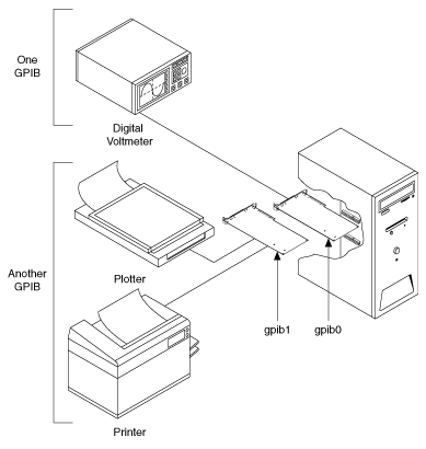
Multiboard drivers, such as the NI-488.2 driver for Windows, can control more than one interface board. The following picture shows an example of a multiboard system configuration. gpib0 is the access board for the voltmeter, and gpib1 is the access board for the plotter and printer. The control functions of the devices automatically access their respective boards.

Configuration Requirements
To achieve the high data transfer rate that the GPIB was designed for, you must limit the physical distance between devices and the number of devices on the bus. The following restrictions are typical:
- A maximum separation of 4 m between any two devices and an average separation of 2 m over the entire bus.
- A maximum total cable length of 20 m.
- A maximum of 15 devices connected to each bus, with at least two-thirds powered on.
For high-speed operation, the following restrictions apply:
- All devices in the system must be powered on.
- Cable lengths should be as short as possible up to a maximum of 15 m of cable in each system.
- At least one equivalent device load per meter of cable.
If you want to exceed these limitations, you can use bus extenders to increase the cable length or expanders to increase the number of device loads. Extenders and expanders are available from National Instruments.