Measuring Resistance
Power supplies and SMUs are capable of making resistance measurements because they can both generate and measure test voltages and currents. Because they can operate as precision current sources up to 2 A, these modules are well suited to measure low resistance values.
To measure a resistance with an NI power supply or SMU, select a test current that creates a voltage drop within module capabilities. After the channel output is enabled and settled, use the Measure Multiple VI to measure the actual current being delivered to the resistor as well as the measured voltage across the resistor. To determine the accuracy a resistance measurement, the accuracy specifications of both current and voltage measurements for the power supply or SMU should be taken into account. For channels with remote sense capabilities, enabling this feature results in a more accurate voltage measurement at the resistor terminals.
Compensation for Offset Voltages
When measuring low-value resistances thermal voltages may introduce significant offsets into the resistance measurement path. If an offset voltage exists in series with the resistance to be measured as in the following figure, taking a second measurement at a different current output setpoint allows the offset to be accounted for in the resistance calculation.

The two test currents, I1 and I2, create voltage drops of V1 and V2 respectively. Thus, the following two equations can be derived:
V1 = I1R + VOS
V2 = I2R + VOS
Rearranging these two equations allows for the calculation of the unknown resistance R without measuring VOS. Assuming the currents I1 and I2 are different the following equation can be derived:

For the best signal-to-noise performance, test currents of opposite polarity should be used (for example, + 100 mA and 100 mA). If currents of opposite polarity are not feasible, the next best solution is to use test currents that are 100x apart (that is, if your first current is 1 A, you should choose a second test current of 0.01 mA).
Resistor Self-Heating
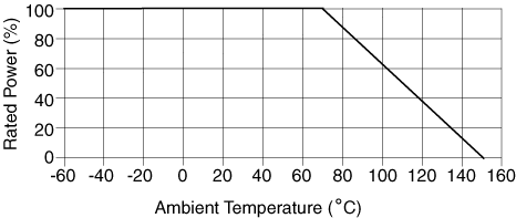
As power dissipation in a resistor increases, the temperature of the resistor increases and causes a change in the resistance value. You can calculate how much error is introduced in your measurement by resistor self-heating from the derating curve of Rated Power(%) vs. Ambient Temperature commonly given in resistor specifications.
The specifications of resistors include a derating curve, similar to the one shown in the following graph. Notice that this curve does not show the temperature change of the resistor due to self-heating. The curve shows the percentage of the rated power that you can apply to a resistor vs. the ambient temperature. So at 70 °C of ambient temperature, you can apply up to 100% of the rated power, but at 100 °C you can only apply up to 65% of the rated power.

At any temperature, the resistor will have a temperature change due to self-heating (ΔTSH), so the actual temperature of the resistor is the ambient temperature plus an unknown ΔTSH. Even though this graph does not directly show the value of ΔTSH, you can still calculate it.
Notice that at 70 °C, applying 100% of the rated power, the temperature of the resistor is equal to 70 °C plus ΔTSH. At 150 °C, you cannot apply any power to the resistor, so the temperature of the resistor is equal to the ambient temperature. You can thus infer that when applying 100% of the rated power at 70 °C the total temperature of the resistor is 150 °C. Therefore, above 70 °C, the value of ΔTSH increases in such a way that when you add to it the ambient temperature it surpasses 150 °C. Therefore, you need to limit the power you apply to the resistor to keep the total temperature of the part under 150 °C. Hence, the value of ΔTSH is a function of the power applied to the part.
The thermal resistance (θ) is equal to the absolute value of the slope between the 70 °C and the 150 °C points in the derating curve shown above.
θ = (150 °C—70 °C)/ΔP = (150 °C—70 °C/)Pmax) °C/W
If the resistor has a Rated Power at 70 °C equal to 0.25 W, then the value for θ would be equal to:
θ = (150 °C—70 °C)/ΔP = (150 °C—70 °C)/250 mW = 80 °C/(250*10–3 W) = 320 °C/W = 0.32 °C/mW
To decrease the thermal resistance, you must look for a resistor with higher rated power, or find a way to "heat sink" the resistor to the environment. This can become complicated and expensive unless the resistor is specifically designed for heat sinking.
You can now calculate the change in temperature due to power dissipation using the thermal resistance (θ) and the power being dissipated in the resistor (product of voltage and current). Then you can use the temperature coefficient of the resistor (usually given in ppm/ °C) to calculate the change in the resistance value.
Resistor self-heating is more relevant when measuring currents above 400 mA. The self-heating of the current shunts in the largest current ranges for the NI PXI-4110/4130 cause an additional derating on those modules in these current ranges. For more information about additional derating in these ranges, refer to your device specifications document. To minimize the self-heating effect of current shunts for the largest current ranges in these devices, measurements should be made as soon as possible after enabling the output, before the shunt has had the opportunity to heat itself.