Local and Remote Sense
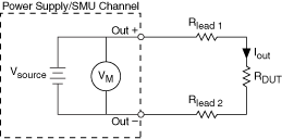
A measurement made with local sense uses a single set of leads for output and voltage measurement, as illustrated in the following figure:

An error in the DUT voltage measurement is due to the output current and the resistance of the leads used to connect the power supply or SMU to the load. This error can be calculated using the following equation:
Local Sense Error (Volts) = Iout(Rlead1 + Rlead2)
When the device is operating in Constant Voltage mode, local sense forces the requested voltage at the output terminals of the device. The actual voltage at the DUT terminals is lower than the requested output because of the output lead resistance error.
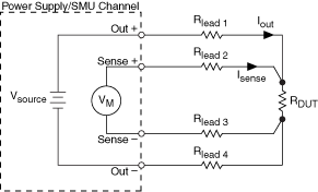
Measurements made using remote sense, sometimes referred to as 4-wire sense, require 4-wire connections to the DUT (and 4-wire switches if a switching system is used to expand the channel count). Using remote sense offers the benefit of more accurate voltage output and measurements when the output lead voltage drop is significant. In a remote sense configuration, one set of leads carries the output current, while another set of leads is used to measure voltage directly at the DUT terminals, as illustrated in the following figure:

Although the current flowing in the output leads can be several amps or more depending on the power supply or SMU, a very small amount of current flows through the sense leads resulting in a much smaller voltage drop error for measurements versus the local sense error. When using remote sense in the DC Voltage output function, the output voltage is forced at the end of the sense leads instead of the output terminals. When using remote sense in the DC Current output function, the voltage limit is measured at the end of the sense leads instead of at the output terminals. Using remote sense results in a voltage at the DUT terminals that is more accurate than what can be achieved using local sense. Ideally, the sense leads should be connected as close to the DUT terminals as possible.
When using remote sense, it is important to remember that the magnitude of the voltage drop across the higher current output leads is usually limited to one or two volts per lead, depending on the power supply or SMU. When attempting to force a voltage using the DC Voltage output function, dropping more voltage across the output leads than the specified maximum in remote sense mode may result in a voltage at the load that is less than the requested level. When attempting to force a current using the DC Current output function while using either local or remote sense, excessive line drop may force the power supply or SMU into Constant Voltage mode before the requested current level can be reached.
Configuring a channel for remote sense operation without connecting the sense leads to the DUT can result in measurements that do not meet the published specifications. If a channel is configured for remote sense and the remote sense leads are left open, the channel may source a voltage as large as 20% higher than the voltage level or voltage limit.
Refer to your device specifications document for more information about remote sense support and the maximum output lead voltage drop allowed.
Remote sense can be enabled or disabled using the niDCPower Configure Sense VI, or the niDCPower_ConfigureSense function on a per output basis for channels that support this feature.
| Devices with Remote Sense Capabilities | |
|---|---|
| Device | Channel(s) |
| NI PXI-4130 | 1 |