Designing a Fixed-Point Filter Part 3: Quantizing a Floating-Point Filter (Digital Filter Design Toolkit)
In Part 2 of this tutorial, you scaled the coefficients of the reference floating-point filter. In Part 3 of this tutorial, you quantize the coefficients of the filter.
Quantization is the process of approximating a fixed-point value for each reference floating-point value. You then can use the fixed-point values in fixed-point mathematical computation or a hardware implementation. By quantizing the coefficients of the reference floating-point filter, you convert a floating-point filter to a fixed-point filter.
 |
Note If you did not complete Part 2 of this tutorial, refer to labview\examples\Digital Filter Design\Getting Started\Tutorials\Designing a Fixed-Point Filter\Designing a Fixed-Point Filter Part 2.vi for a completed version of the digital filter from that part. |
Complete the following steps to quantize a floating-point filter by using the DFD FXP Quantize Coef VI.
- Place the DFD FXP Quantize Coef VI on the block diagram.
 Place
Place
 Find
Find
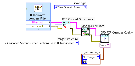
- Wire the filter out and error out outputs of the DFD Scale Filter VI to the filter in and error in inputs of the DFD FXP Quantize Coef VI.
- Right-click the gain settings input of the DFD FXP Quantize Coef VI and select Create»Constant from the shortcut menu.
A block diagram constant appears below the DFD FXP Quantize Coef VI. This constant represents the filter gain settings. - Click the gain settings constant to specify whether this VI processes the filter gain on a host machine or a fixed-point target. If you set gain settings to On Target, you can specify the word length, in number of bits, that represents the filter gain.

Note This tutorial uses On Target and 16 as the gain settings.
The block diagram now resembles the following figure.
- (Optional) Right-click the coefficients b/v word length input of the DFD FXP Quantize Coef VI and select Create»Constant from the shortcut menu.
A block diagram constant appears above the DFD FXP Quantize Coef VI. This constant represents the coefficients word length, in number of bits, that this VI uses to quantize the coefficients b/v. The default value for the word length is 16. Later in the design process, you can change the value for the word length if the filter design does not meet the filtering requirements. - Select File»Save to save the VI.
 |
Note Refer to labview\examples\Digital Filter Design\Getting Started\Tutorials\Designing a Fixed-Point Filter\Designing a Fixed-Point Filter Part 3.vi for a completed version of the digital filter from this part of the tutorial. |
| Previous: Scaling Filter Coefficients | Next: Analyzing a Fixed-Point Filter |