Designing a Fixed-Point Filter Part 1: Selecting a Filter Structure (Digital Filter Design Toolkit)
In fixed-point implementations, different filter structures have different memory and multiplier requirements. These requirements can cause different finite word length effects. In this situation, converting the default filter structure of a filter design to a different structure might provide better finite word length performance.
In Part 1 of this tutorial, you select a filter structure for the reference floating-point filter. Later in the design process, you can change the implementation structure if the filter design does not meet the filtering requirements.
Complete the following steps to select a filter structure for the reference floating-point filter by using the DFD Convert Structure VI.
- Design a reference floating-point filter, if you have not already done so. This tutorial uses the lowpass Butterworth filter from Part 1 of the Designing a Floating-Point Filter tutorial.

Note Refer to labview\examples\Digital Filter Design\Getting Started\Tutorials\Designing a Floating-Point Filter\Designing a Floating-Point Filter Part 1.vi for the reference floating-point filter you use in this tutorial. - Place the DFD Convert Structure VI on the block diagram.
 Place
Place
 Find
Find
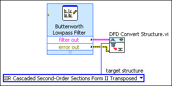
- Wire the filter out and error out outputs of the Classical Filter Design Express VI to the filter in and error in inputs of the DFD Convert Structure VI.
- Right-click the target structure input of the DFD Convert Structure VI and select Create»Constant from the shortcut menu.
A block diagram constant appears to the left of the DFD Convert Structure VI. This constant represents the target structure that this VI uses to convert the filter structure. - Click the target structure constant to select the target structure this VI uses to convert the filter structure.

Note This tutorial uses the IIR Cascaded Second-Order Sections Form II Transposed structure, which is the default structure for Butterworth filters.
The block diagram now resembles the following figure.
- Select File»Save As and save this VI as Designing a Fixed-Point Filter.vi in an easily accessible location.
After you select a filter structure for the reference floating-point filter, you can scale the filter coefficients in Part 2 of this tutorial.
 |
Note Refer to labview\examples\Digital Filter Design\Getting Started\Tutorials\Designing a Fixed-Point Filter\Designing a Fixed-Point Filter Part 1.vi for a completed version of the digital filter from this tutorial. |
| Previous: Designing a Fixed-Point Filter | Next: Scaling Filter Coefficients |