I/Q Data
From LabView Modulation Toolkit
I/Q Data
I/Q data is an alternative method of describing the magnitude and phase data of a signal.
A sinusoidal wave can be written in polar coordinate form as shown in the following equation:
f(t) = Acos(2![]() ft + φ)
ft + φ)
where
A is the amplitude
2![]() f is the frequency
f is the frequency
φ is the phase
A sinusoidal wave can also be represented in a complex Cartesian coordinate system by its real and complex components such that the in-phase (I) component can be written as
I(t) = Acos(φ)cos(2![]() ft)
ft)
and the quadrature (Q) component can be written as
Q(t) = Asin(φ)sin(2![]() ft)
ft)
Graphically, I and Q projections of the polar coordinate sinusoidal wave are on the x and y axis, respectively, as illustrated in the following graph.
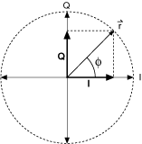
In the preceding figure, the sinusoidal wave frequency is shown as the rotational rate of the vector ![]() around the circle.
around the circle.
The vector magnitude (M) is given by
M = (I(t)2 + Q(t)2)1/2
and the vector phase is given by
φ = tan–1(Q/I).
While magnitude and phase data seem more intuitive, hardware design concerns make I and Q data the better choice for RF waveforms. I/Q representation provides an effective way to visualize and measure the quality of modulation. The following figure is a generic block diagram of an I/Q demodulator, which takes an RF signal and separates out the I and Q component from that incoming RF signal.
The following figure is a generic block diagram of an I/Q demodulator.
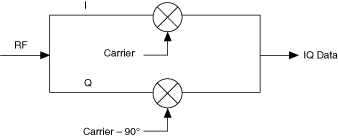
The circles with an 'X' represent mixers. The I/Q modulator is represented here as part of a downconverter module. The incoming message signal splits and one signal is multiplied by an in-phase carrier signal (I) while the other signal is multiplied by a quadrature signal (Q). This multiplication separates the in-phase and quadrature components from the incoming signal.