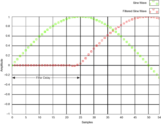
Filter Delay
Modulation Toolkit uses finite impulse response (FIR) filters for different operations like pulse-shaping, matched, and downconversion filtering. For such filters, the output signal is related to the input signal as shown by the following equation:
y[n] = b0x[n] + b1x[n-1] + ... + bPx[n-P]
where P is the filter order
x[n] is the input signal
y[n] is the output signal
bi are the filter coefficients
The initial state for all samples in an FIR filter is 0. The filter output until the first input sample reaches the middle tap (the first causal sample) is called the transient response, or filter delay. Given an FIR filter which has N taps, the delay is (N - 1)/2 samples. This relationship is illustrated in the following figure, where a sine wave is filtered by an FIR filter with 50 taps.

Using the Reset? Parameter in Iterative Modulator/Demodulator Operation
In the Modulation Toolkit, digital modulation VIs initially perform mapping of the input bits onto symbols and subsequently apply a pulse-shaping filter to these symbols. The digital demodulation VIs perform matched filtering and buffering on the recovered complex waveform. Some useful samples are held in these filters.
In an iterative operation where the modulator/demodulator is called repeatedly inside a loop to operate on blocks of bits/symbols (all of which are part of the same message), two options are possible:
- reset? is set to TRUE on every iteration—The filters in the modulator/demodulator are initialized with zeros on every iteration of the loop, and the returned output data is shortened by (N - 1)/2 symbols on all iterations.
- reset? is set to TRUE on the first call and to FALSE on subsequent iterations—The filters in the modulator/demodulator are initialized with zeros on the first iteration of the loop. On subsequent iterations of the loop, the VI uses state information from previous iterations to initialize the filter.
Recovering Samples in Single Shot Operations
In single-shot operations for modulators and demodulators, the filter delay is truncated before the signal is generated because these samples are not valid. Some samples at the end of the block do not appear at the modulator/demodulator output, and hence appear to have been lost.
You can recover these samples by sending extra samples to the modulator/demodulator. To determine how many extra samples you must added, use the following guidelines:
- For Modulation VIs—Let L = pulse-shaping filter length, m = number of samples per symbol, and M = modulation order. The number of bits to be added to the input bit stream is given by the following formula:

- For Demodulation VIs—The demodulation VIs use filters during matched filtering.
Let L be the length of the matched filter. The number of samples to be added to the input signal prior to filtering is given by the following formula:

The N extra samples are obtained by repeating the last sample value of the input signal N times to ensure signal continuity.
Working with Filter Delay in Modulation Toolkit 4.1
Modulation
The modulation VIs in Modulation Toolkit 4.1 contain a new parameter, flush buffers?, that allows you to flush out samples that have been delayed in the pulse-shaping filter. When this parameter is set to TRUE, the VI internally pads the input data to recover any lost data. Set this parameter to TRUE for single-shot applications and during the last iteration of a continuous operation application.
Demodulation
Modulation Toolkit 4.1 provides two methods for demodulation: demodulation VIs and detector VIs. The demodulation VIs contain the same behavior as in Modulation Toolkit 4.0, that is, they allow you to recover the time-aligned demodulated waveform, the demodulated information bit stream, and measurement results obtained during demodulation. The detector VIs return only the demodulated bit stream. These new VIs contain the flush buffers? parameter that pads the incoming samples and forces out the samples delayed because of the FIR filters used in the demodulation algorithms.
 |
Note Setting flush buffers? to TRUE destroys the internal states of the algorithms such that you will be unable to perform continuous processing on the signal during subsequent iterations. If flush buffers? is set to TRUE, you must set reset? to TRUE on the subsequent iteration. |