Glossary
From LabView Modulation Toolkit
Glossary
Prefixes
| Symbol | Prefix | Value |
|---|---|---|
| n | nano | 10 -9 |
| µ | micro | 10 -6 |
| m | milli | 10 -3 |
| k | kilo | 10 3 |
| M | mega | 10 6 |
| G | giga | 10 9 |
Numbers/Symbols
| nV | nanovolts | 10-9 volts |
| µV | microvolts | 10-6 volts |
| µΩ | microohms | 10-6 ohms |
| mΩ | milliohms | 10-3 ohms |
| MΩ | megaohms | 106 ohms |
| nA | nanoamps | 10-9 amperes |
| µA | microamps | 10-6 amperes |
| mA | milliamps | 10-3 amperes |
A | |||||||||
| amplitude droop | Measured in dB, is a measure of the amount that the signal power falls from the start of a specified measurement window (di) to the end of that window (df). | ||||||||
| amplitude modulation (AM) | A process that varies the amplitude of an radio frequency (RF) carrier signal according to the amplitude of the message signal. | ||||||||
| amplitude-shift keying (ASK) | Refers to a type of amplitude modulation which assigns bit values to discrete amplitude levels. The carrier signal is then modulated among the members of a set of discrete values to transmit information. | ||||||||
| analog-to-digital converter (ADC) | A hardware component that converts analog voltages to digitized values. An ADC can convert an analog signal to a digital signal representing equivalent information. | ||||||||
B | |||||||||
| bit error rate (BER) | The ratio of erroneous bits to total bits transmitted, received, or processed over some stipulated period. Transmission BER expresses the number of erroneous bits received divided by the total number of bits transmitted. Information BER expresses the number of erroneous decoded (corrected) bits divided by the total number of decoded (corrected) bits. | ||||||||
| burst timing | For burst signals, burst timing refers to the location of the burst, obtained by its correlation against an ideal power curve. In addition, an upper and lower mask are used for testing whether the burst signal satisfies mask specifications. The following figure shows upper mask, lower mask, and ideal power curve. | ||||||||
C | |||||||||
| Carson's Rule | Defines the approximate modulation bandwidth required for a carrier signal that is frequency-modulated by a spectrum of frequencies rather than a single frequency. The Carson bandwidth rule is expressed by the relation CBR = 2(Δf + fm) where CBR is the bandwidth requirement, Δf is the carrier peak deviation frequency, and fm is the highest modulating frequency. | ||||||||
| CCDF measurement | The complementary cumulative distribution function (CCDF) is a statistical characterization of the time-domain waveform that completely describes the power characteristics of a signal. | ||||||||
| center frequency | The middle frequency of the channel bandwidth. In frequency modulation, the center frequency is equal to the rest frequency—specifically, the frequency of the unmodulated carrier wave. | ||||||||
| code word | The generated coded bits/numbers from a channel coding system. | ||||||||
| complex envelope | A complex representation of the baseband modulated signal. | ||||||||
| component | The real and imaginary parts of a complex number are referred to as components. Modulation Toolkit VIs can use complex components to describe signal properties.
For example, you can represent a two-dimensional vector of length S by its components S = A + iB, where A and B are the vector x- and y-components. The real part of the vector corresponds to the x-component (A), while the imaginary part corresponds to the y-component (B). | ||||||||
D | |||||||||
| data word | The incoming message bits to a channel coding system. | ||||||||
| DC offset | A complex signal impairment that shifts the locus of ideal symbol coordinates off-center in the I/Q plane. A DC offset can be added to the baseband I component, the Q component, or both. The DC offset can be either positive or negative, with the sign indicating direction of the shift. DC offset is expressed as a percentage of full scale, where "full scale" (fs) is the amplitude of the baseband QM waveform. | ||||||||
| depuncture | The process of inserting erasure values into the input data stream prior to its input to the decoder. If the input data is real-valued BPSK modulated data (as in the case of unquantized symbol decisions from a demodulator or equalizer), the erasure values equal 0. If the input data stream consists of quantized integers coming from an A/D converter (ADC) at the output of a demodulator, the erasure values correspond to the integer representation that is half the maximum output sample value generated by the analog-to-digital conversion process. | ||||||||
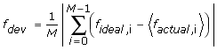
| deviation error | For an M-FSK system, the average deviation error is defined as the average magnitude of the spread of the FSK demodulated symbol spaced waveform around the ideal symbol (frequency) locations.
Mathematically, the deviation error is defined as:
where M is the FSK modulation format, ƒideal,i is the ideal symbol location at the FSK frequency corresponding to location i, and <ƒactual,i> is the mean value of the demodulated symbols at location i. | ||||||||
| digital-to-analog converter | A hardware component that converts digital values to analog voltages. Thus a DAC can convert a digital signal to an analog signal representing equivalent information. | ||||||||
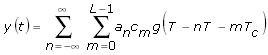
| direct sequence spread spectrum (DSSS) | A process by which data is transmitted using a higher bandwidth signal that is demanded by the data rate. Using DSSS allows multiple channels to occupy the same bandwidth, mitigating interference from other users at the expense of bandwidth expansion.
DSSS is accomplished by spreading each bit of signal data is spread at the transmitter into L chips, using a pseudorandom L-chip spreading code called a code word. The length L of the pseudorandom spreading code is also known as the bandwidth expansion factor because the chips are transmitted at a rate equal to L × bit rate of the data. The spreading code appears random to all receivers except the intended one, which uses the knowledge of the spreading code to demodulate and recover the transmitted information. Thus multiple channels can occupy the same portion of the frequency spectrum by using code words that have little or no correlation with one another, and little or no autocorrelation for any shift other than zero. Mathematically, a DSSS signal is described by:
where
y(t) is the transmitted DSSS signal | ||||||||
| downconverter | A signal conditioning device that converts a specific band of high-frequency (RF) signals to more manageable intermediate frequencies (IF) that can be digitized. | ||||||||
F | |||||||||
| frequency | Refers to a basic unit of rate measured in events or oscillations per second. Frequency also refers to a number representing a specific point in the electromagnetic spectrum. | ||||||||
I | |||||||||
| information signal | Contains the data for transmission. The information signal is used to modulate the carrier wave to create the modulated wave for transmission. The information signal data is recovered from the modulated wave by a process of demodulation.
The information signal is often referred to as the baseband signal or message signal. | ||||||||
| interleaver | A device that ensures the symbols from several different code words are well separated during transmission over a single path, so that the symbols from any given code word are clearly received in time-division sequence. Interleavers are used in conjunction with error-correcting codes to counteract the effects of burst errors. | ||||||||
M | |||||||||
| message signal | Contains the data for transmission. The message signal is used to modulate the carrier wave to create the modulated wave for transmission. The message signal data is recovered from the modulated wave by a process of demodulation.
The message signal is often referred to as the baseband signal or information signal. | ||||||||
| mixer | A nonlinear analog circuit that multiplies two signals. Mixers are typically used to shift signal frequencies. A mixer receives two sinusoidal input signals at different frequencies and returns a signal with components at frequencies equal to the sum and difference of the two original input frequencies. Nonlinear mixers are used when performing amplitude modulation of RF carrier signals. | ||||||||
N | |||||||||
| noise figure (NF) | The ratio of the actual output noise to the noise that would remain if the instrument did not contribute its own thermal noise. In heterodyne systems, output noise power includes spurious contributions from image-frequency transformation. However, the portion attributable to thermal noise in the input termination includes only what appears in the output due to the principal frequency transformation of the system, and it excludes what appears via the image frequency transformation. | ||||||||
O | |||||||||
| offset quadrature phase-shift keying (OQPSK) | A variant of phase-shift keying modulation using 4 different values of the phase to transmit the signal. This scheme is sometimes referred to as staggered quadrature phase-shift keying (SQPSK). | ||||||||
P | |||||||||
| phase-locked loop (PLL) | An electronic circuit that controls an oscillator so that the circuit maintains a constant phase angle relative to a reference signal. | ||||||||
| puncture | The process of artificially increasing the code rate of the data stream, generated from a block or convolutional encoder, by selectively deleting certain elements in the data stream. | ||||||||
R | |||||||||
| radio frequency (RF) | refers to the radio frequency range of the electromagnetic spectrum. RF is often used to describe a range of sub-infrared frequencies from the tens of MHz to several GHz. | ||||||||
| RF signal analyzer (RFSA) | refers to a family of PXI and PXI Express (PXIe) devices that include the NI PXI-5660, the NI PXI-5661, and the NI 5663 RF vector signal analyzers.
The NI 5660 uses the ni5660 Vis in LabVIEW and the NI-TUNER and NI-SCOPE instrument drivers in C, C++, and LabWindows™/CVI™. The NI 5661 and NI 5663 use the NI-RFSA driver for controlling the RF downconverter module, the RF digitizer module, and an LO source (NI 5663 only). All NI RF signal analyzers include the NI Spectral Measurements Toolkit for performing frequency-domain analysis, and modulation VIs for performing analog modulation and demodulation measurements. | ||||||||
S | |||||||||
| sample rate | The sample rate is the rate at which a device acquires an analog signal, expressed in samples per second (S/s). The sample rate is usually the clock speed of the analog-to-digital converter (ADC). | ||||||||
| signal-to-noise ratio (SNR) | The ratio of the desired signal amplitude to the noise signal amplitude at a given point in time. SNR is expressed as 20 times the logarithm of the amplitude ratio, or 10 times the logarithm of the power ratio. SNR is usually expressed in dB and in terms of peak values for impulse noise and root mean square (RMS) values for random noise. In defining or specifying the SNR, specify the signal and noise characterizations, for example, peak-signal-to-peak-noise ratio to avoid ambiguity. | ||||||||
| signal-to-quantized-noise ratio (SQNR) | A measurement of the effect of quantization errors introduced by analog-to-digital conversion at the analog-to-digital converter (ADC). Exceeding the SQNR of your instrument clips the signal. | ||||||||
| spectral density | A measure of total signal power in a specified spectral bandwidth divided by the bandwidth, expressed in watts per hertz (W/Hz). | ||||||||
| symbol rate | Expresses the number of symbols transmitted per second (symbols/s). To convert symbol rate into bit rate, which expresses the number of bits transferred per second, multiply the symbol rate by the number of bits per symbol used in the digital modulation scheme of interest. Symbol rate is also known as baud rate. | ||||||||