Types of Simulation Subsystems (Control Design and Simulation Module)
Simulation subsystems provide a way to modularize simulation diagram code. By combining several functions into a subsystem, you reduce the amount of space needed on the simulation diagram, making the simulation easier to navigate visually. Simulation subsystems also are useful for validating, distributing, and reusing portions of the simulation diagram.
You can use many Simulation VIs and functions only on a simulation diagram, such as within a Simulation Loop. Because simulation subsystems modularize simulation diagram code, you can use the Simulation VIs and functions in simulation subsystems as well. The entire block diagram of a simulation subsystem is pale yellow like the inside of a Simulation Loop. When you use Simulation VIs and functions in a simulation subsystem, you place the VIs and functions directly on the subsystem block diagram rather than within a Simulation Loop.
You can run simulation subsystems as stand-alone VIs, within a Simulation Loop or another simulation subsystem, or on a block diagram outside a Simulation Loop.
Running a Subsystem as a Stand-Alone VI
When you run a simulation subsystem as a stand-alone VI, you configure the simulation parameters by selecting Operate»Configure Simulation Parameters to launch the Configure Simulation Parameters dialog box. You also can configure the execution and appearance of the subsystem by selecting File»VI Properties.
When running a simulation subsystem as a stand-alone VI, you can use standard LabVIEW debugging techniques, such as execution highlighting, breakpoints, probes, and single-stepping. You cannot use these techniques on a subsystem that is within another Simulation Loop. You also cannot step into the subsystem. However, you can set a breakpoint on the entire subsystem by right-clicking the subsystem and selecting Breakpoint»Set Breakpoint from the shortcut menu. You also can use a probe or a custom probe to monitor the subsystem output.
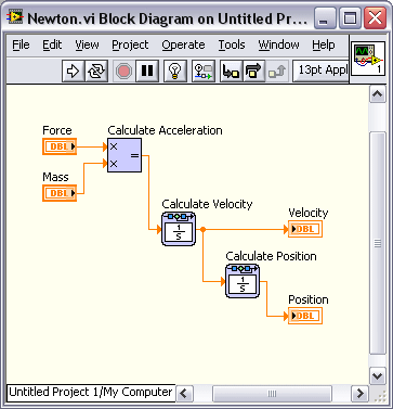
The following figure shows the simulation diagram of a simulation subsystem Newton.vi, which obtains the position of a mass by using Newton's Second Law of Motion.

In the previous figure, this subsystem has front panel controls and indicators, so you can run this subsystem by clicking the Run button. Because Newton.vi does not have a Simulation Loop, you configure the parameters of this subsystem by selecting Operate»Configure Simulation Parameters.
Running a Subsystem in a Simulation Loop
If you run a simulation subsystem inside a Simulation Loop, the simulation subsystem inherits the parameters from the Simulation Loop.
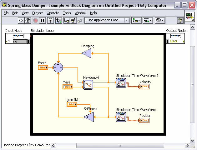
The following figure shows Newton.vi included within the Simulation Loop of another simulation diagram.

In the previous figure, the parameters of the Simulation Loop override any parameters you configured specifically for Newton.vi.
 |
Note You create this subsystem and this VI in the Getting Started with Simulation tutorial. |
Running a Subsystem Outside a Simulation Loop
If you run a simulation subsystem on a block diagram outside a Simulation Loop, the simulation subsystem executes one step of the ordinary differential equation (ODE) solver each time the simulation subsystem is called. For example, if you place the simulation subsystem in a Timed Loop, one step of the ODE solver executes at each iteration of the loop. You can use only fixed step-size ODE solvers for a simulation subsystem outside a Simulation Loop. Specify the time step using the Step Size (s) configuration option of the subsystem.
 |
Tip If you create an application with a simulation subsystem inside a Timed Loop and then deploy the application to a real-time target, set the Step Size (s) of the subsystem equal to the period of the Timed Loop. |
When you place a simulation subsystem on a block diagram outside a Simulation Loop, the icon of the simulation subsystem appears in the Express style by default. You can wire values to the parameters of the simulation subsystem to configure the simulation subsystem programmatically.
 |
Note The Static and Dynamic icon styles are disabled for subsystems outside a Simulation Loop. |
You also can configure the parameters of the simulation subsystem interactively. Double-click the simulation subsystem to launch the configuration dialog box of that simulation subsystem. In this configuration dialog box, you can configure the specific parameters of the simulation subsystem as well as the following general simulation parameters:
- Initial Time (s)—Specifies the time at which to start the ODE solver.
- ODE Solver—Specifies the type of ODE solver the simulation uses.
- Nan/Inf Check—Specifies that you want the Control Design and Simulation Module to check the simulation values for not a number (NaN) and infinite (Inf) values. The Control Design and Simulation Module returns an error if it encounters a NaN or Inf value.
- Step Size (s)—Specifies the interval, in seconds, between the times at which the ODE solver evaluates the model and updates the model output.
- Discrete Step Size (s)—Specifies the base time step size, in seconds, for the simulation.
- Auto Discrete Time—Automatically calculates the Discrete Step Size (s).
These parameters are identical to parameters you can configure in the Configure Simulation Parameters dialog box of a Simulation Loop. In the configuration dialog box of a simulation subsystem, these parameters appear as sub-items of the Simulation Parameters item in the Parameters tree. If the simulation subsystem already contains a parameter with the same name as one of the general simulation parameters listed above, LabVIEW appends the general simulation parameter name with an underscore.
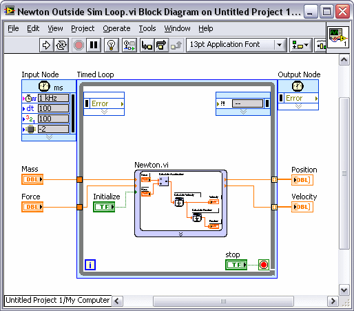
The following figure shows Newton.vi on a block diagram outside a Simulation Loop.

In the previous figure, the Timed Loop determines when Newton.vi executes the next step of the ODE solver. Because Newton.vi is outside a Simulation Loop, you can configure the simulation parameters, including the ODE solver to use, by double-clicking the simulation subsystem.
If you run a simulation subsystem outside a Simulation Loop, you can reinitialize the simulation subsystem by setting the Initialize input of the simulation subsystem to TRUE. This input restarts the ODE solver from the specified Initial Time (s). The Initialize input is available for a simulation subsystem only when the subsystem is not inside a Simulation Loop or another simulation subsystem.
Polymorphic Subsystems
If you create one or more subsystems that perform the same operation on different data types, you can package those subsystems together to create a polymorphic subsystem. A polymorphic subsystem is a single VI that points to one or more subsystems, called instances. Each instance accepts a different data type for a single input or output terminal. LabVIEW automatically selects the correct instance based on the input data type.
For example, one subsystem could operate on a double-precision floating point number, while another subsystem performs the same operation on a 16-bit integer. Instead of placing both subsystems on the simulation diagram, you can create a polymorphic subsystem that automatically chooses the correct instance.
For a polymorphic subsystem to work, each instance of the polymorphic subsystem must be a simulation subsystem. You cannot create a polymorphic subsystem with both VIs and subsystems as instances. Also, each subsystem must have an identical connector pane pattern. Additionally, the names of corresponding input parameters for each instance must be identical.