Configuring Simulation Parameters (Control Design and Simulation Module)
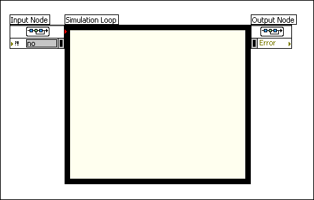
The Simulation Loop, shown in the following figure, contains the parameters that define the behavior of the simulation.

You can configure these simulation parameters by using the following two methods:
- Using the Configure Simulation Parameters dialog box
- Wiring values to the Input Node
You also can use a combination of these two methods in the same simulation diagram. However, values that you programmatically configure override any equivalent settings that you make in the Configure Simulation Parameters dialog box.
 |
Tip Use the Output Node to view any errors that occur during the execution of the Simulation Loop. Use the Get Simulation Parameters function to display the parameters you configure for the simulation. |
The Simulation Loop is a version of the Timed Loop. Both loops can iterate deterministically according to a period and priority you define. However, the Simulation Loop also executes the simulation diagram according to the ordinary differential equation (ODE) solver you choose. The inside of the Simulation Loop also has a pale yellow background to distinguish the simulation diagram from the LabVIEW block diagram. Similar to other loops and structures, you can use tunnels to pass data in and out of the Simulation Loop.
Configuring Simulation Parameters Programmatically
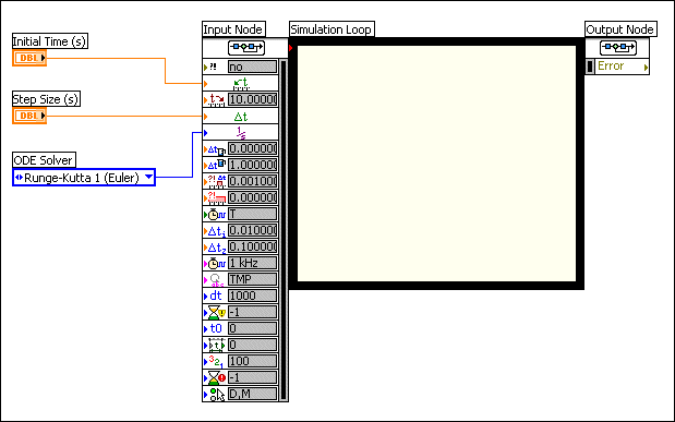
The following figure shows how you configure a simulation diagram programmatically.

The previous figure shows how the gray boxes on the Input Node display any values that you configure in the Configure Simulation Parameters dialog box. Values that you configure programmatically do not have gray boxes.