IMAQ Generate Pulse3 VI

NI-IMAQ VI

IMAQ Generate Pulse3 VI

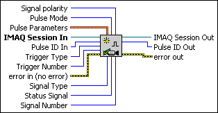
Installed With: NI Vision Acquisition Software

Generates a pulse on a trigger line. IMAQ Generate Pulse3 can generate a pulse immediately or on the assertion edge of a status or trigger signal. Each trigger pulse uses a Pulse ID, which is automatically generated each time you call this VI.

Details

IMAQ Generate Pulse3

cu32.gif

Signal polarity specifies the polarity of the status or trigger signal parameter.

The following values are valid:

Rising Edge (0)

Sets the signal polarity to rising edge.

Falling Edge (1)

Sets the signal polarity to falling edge.

cu32.gif

Pulse Mode specifies if the pulse is repeated.

The following values are valid:

Pulse train (0)

Generates a continuous pulse train on the first assertion edge of the pulse stimulus signal.

Single pulse (1)

Generates a single pulse on the first assertion edge of the pulse stimulus signal.

Rearmed pulse (2)

Generates a single pulse on all assertion edges of the pulse stimulus signal.

Stop (3)

Stops the pulse generation.

cnclst.gif

Pulse Parameters specifies the parameters used to describe a pulse.

cdbl.gif

Pulse Delay is the desired duration of the first phase of the signal in seconds. If the Units specified are seconds, the Pulse Delay should be greater than 0. If the Units specified are Scaled Encoder, the Pulse Delay uses one cycle when 0 is specified.

cdbl.gif

Pulse Width is the desired duration of the second phase of the signal in seconds. If the Units specified are seconds, the Pulse Width should be greater than 0. If the Units specified are Scaled Encoder, the Pulse Width uses one cycle when 0 is specified.

cenum.gif

Pulse Polarity is the polarity of second phase (period two) of each delayed pulse.

cenum.gif

Units Specifies the units for the Pulse Delay and Pulse Width parameters. If Scaled Encoder Counts is selected, Pulse Delay and Pulse Width must be integral values.

crn.gif

IMAQ Session In identifies the device.

ci32.gif

Pulse ID In identifies the Pulse Id input. This parameter is used only when Mode is set to Stop.

cu32.gif

Trigger Type specifies the type of the trigger signal.

The following values are valid:

Note  To use the ISO_IN or RS422_IN signals on the NI PCI-1426, select External as the Trigger Type for your function and choose ISO IN or RS-422 as the Signal Level for the trigger line in Measurement & Automation Explorer (MAX).
External (0)

Use an external trigger for the trigger.

RTSI (1)

Use an RTSI line for the trigger.

ISO Out (3)

Use an isolated output for the trigger.

cu32.gif

Trigger Number specifies the number of the trigger.

cerrcodeclst.gif

error in (no error) describes error conditions that occur before this VI or function runs. The default is no error. If an error occurred before this VI or function runs, the VI or function passes the error in value to error out. This VI or function runs normally only if no error occurred before this VI or function runs. If an error occurs while this VI or function runs, it runs normally and sets its own error status in error out. Use the Simple Error Handler or General Error Handler VIs to display the description of the error code. Use error in and error out to check errors and to specify execution order by wiring error out from one node to error in of the next node.

cbool.gif

status is TRUE (X) if an error occurred before this VI or function ran or FALSE (checkmark) to indicate a warning or that no error occurred before this VI or function ran. The default is FALSE.

ci32.gif

code code is the number identifying an error or warning. If status is TRUE, code is a non-zero error code. If status is FALSE, code can be zero or a warning code. Use the error handler VIs to look up the meaning of this code and to display the corresponding error message.

cstr.gif

source describes the origin of the error or warning and is, in most cases, the name of the VI or function that produced the error or warning. The default is an empty string.

cu32.gif

Signal Type specifies the type of signal that causes the pulse to be generated.

The following values are valid:

Note  To use the ISO_IN or RS422_In signals on the NI PCI-1426, select External as the Trigger Type for your function and select either ISO In or RS-422 In as the Signal Level in Measurement & Automation Explorer (MAX).
External (0)

Specifies the signal type as the external trigger lines.

RTSI (1)

Specifies the signal type as the RTSI trigger lines.

ISO In (2)

Specifies the signal type as the isolated input trigger lines.

Status (4)

Specifies the signal type as one of the Status Signal signals.

cu32.gif

Status Signal specifies the signal that causes the pulse to be generated if Signal Type is set to Status.

The following values are valid:

Note  The Frame start and Frame done signals are not valid for line scan acquisitions unless each buffer is triggered.
Acquisition in progress (15)

Asserts when the acquisition begins.

Acquisition done (8)

Asserts when the entire acquisition is finished.

Horizontal Synchronization Signal (18)

Asserts a horizontal synchronization signal at the beginning of each line by the camera.

Vertical Synchronization Signal (19)

Asserts a vertical synchronization signal at the beginning of each frame by the camera. This value is not applicable to line scan acquisitions.

Frame start (9)

Asserts at the beginning of each frame that is captured.

Frame done (10)

Asserts at the end of each frame that is captured.

Immediate (16)

Asserts immediately.

cu32.gif

Signal Number specifies the number of the trigger line that causes the pulse to be generated if Signal Type is set to one of the trigger types.

irn.gif

IMAQ Session Out has the same value as IMAQ Session In.

iu32.gif

Pulse Id Out identifies the Pulse Id output.

ierrcodeclst.gif

error out contains error information. If error in indicates that an error occurred before this VI or function ran, error out contains the same error information. Otherwise, it describes the error status that this VI or function produces. Right-click the error out indicator on the front panel and select Explain Error from the shortcut menu for more information about the error.

ibool.gif

status is TRUE (X) if an error occurred or FALSE (checkmark) to indicate a warning or that no error occurred.

ii32.gif

code is the error or warning code. If status is TRUE, code is a nonzero error code. If status is FALSE, code is 0 or a warning code.

istr.gif

source describes the origin of the error or warning and is, in most cases, the name of the VI or function that produced the error or warning. The default is an empty string.

Details

Only the NI 1409, NI 1410, NI 1422, NI 1424, NI 1426, NI 1427, NI 1428, NI 1429, NI 1430 and the NI 17xx smart cameras can generate pulses.

  • The NI 1409, NI 1410, NI 1422, NI 1424, NI 1426, and NI 1428 can generate a maximum of 2 pulses.
  • The NI 1427 and NI 1429 can generate a maximum of 3 pulses.
  • The NI 1430 can generate a maximum of 6 pulses.
  • The NI 17xx smart cameras can generate 2 pulses.

These pulse generators can be automatically configured by NI-IMAQ for generating pulses used to control the camera. In these cases, the VI returns the Exhausted Resources error when the total number of pulses is greater than the maximum number of pulses supported.