Profile View
The Profile View provides an interface, where the polyhedral bodies are defined in sets of perpendicular cross sections running through the grid nodes. More profiles can be opened simultaneously, to get better overview over the geometry in both south-north and west-east directions respectively. Copying of the bodies or the whole cross section to the next or previous profile followed up by reshaping of the geometry speeds up the process of model creation. Profile View also shows curves of computed and/or measured and/or difference fields. More fields can be drawn transparently. Geo-referenced bitmaps could be imported into Mod3D, and drawn transparently to the Map View or Profile View. An example would be a geological map shown in Map View, or a seismic section displayed in a selected Profile View. Main geological units could be digitized in Map View, which are shown as check marks to achieve better orientation in the Profile View. The model definition system controls internally the consistency of the polyhedra geometries, or their topology in other words. The controlling system prevents overlapping or crossing of the polyhedra, simplifies reshaping of the existing bodies and reduces time needed for model creation.
Model Modification
SeeHow
to Create / Modify the model? for detailed description.
Field Curves
Field curves on current
profile
are shown by default in following manner:
Modeled field for gravity and magnetics - solid line.
Modeled field for gravity tensor components - dashed line.
Measured field - cross symbols.
Difference field - dashed line.
See Field
Toolbar for details how to show / hide field curves.
RMS & DRV Indicators
RMS indicator shows the Root Mean
Square error of the currently selected difference field(s). To show or
hide the RMS indicator use command from menu Profile \
Show RMS.
DRV indicator shows the "fake derivative" of the
currently selected difference field(s). To show or hide DRV indicator use
command from menu Profile \ Show Derivative. Fake
derivative is an approximation of the exact derivative and is computed as
sum(dFld / dx + dFld / dy) over all points, where
dFld=(Fld(i)-Fld(i-1)) and
Fld(i) is the
selected field in the ith
grid point.
Profile View floating menus.
Depending on where the user clicks the left
mouse button, one can open following floating menus:
-
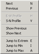
Profile View menu. The default menu displayed, when user click
out of any object.

Menu Item Shortcut Description Next N Moves to the next profile. Previous P Moves to the previous profile.
E-W Profile H Changes the profile orientation to East-West.
S-N Profile V Changes the profile orientation to South-North. Show Previous Shows bodies from prom previous profile on the current profile. Show Next Shows bodies from next profile on the current profile. Jump to Extreme , Min, Max E
I
AGoes to the profile, where the extreme of the selected extreme field is located. To set the extreme field use command Profile \ Set Extreme Field.
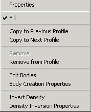
Body menu. Is displayed when user clicks over the body.

Menu Item Description Properties Shows current body properties.
Fill Sets the fill tag. Copy to Previous Profile Use this command to copy the body from current profile to the previous profile. In case of conflict, the problematic vertex is ignored.
Copy to Next Profile Use this command to copy the body from current profile to the next profile. In case of conflict, the problematic vertex is ignored.
Remove Active only if the cursor is over edge (either boundary edge or inner edge).
Remove from Profile Removes the body from the current profile. Edit Bodies Activates Edit Bodies dialog. Body Creation Properties: Use this command to set the body creation properties. Invert Density Use this command to invert the density of the current body. From more details see: Invert Density Properties dialog. Density Inversion Properties Set the settings for density inversion.
-
Body Vertex menu. Is displayed, when user clicks over body
vertex.

Fit Start the vertex fitting. 1D Fit Properties Adjust the settings for 1D vertex fitting.
-
Body Edge. Is the same as Body menu.
-
Insert Body menu. Is displayed, when the user clicks over
vertical line, where the body can be inserted.

Insert New Body Inserts new body to the specified position. Insert Existing Body Inserts existing body to the spefied position.
Edit Bodies Activates Edit Bodies dialog. Body Creation Properties Use this command to set the body creation properties.
Axes
Right mouse button
click on the axis activates the axis properties.
Use left button down + mouse move
to scale the axis interactively.
Shortcuts
Use mouse wheel or arrow
keys to move over the model.