Configuration using PIC24FJ256DA210 Development Board
From MDD File System Interface Library
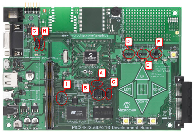
- Before attaching the SD Card PICTail™ Plus Daughter Card to the PIC24FJ256DA210 Development Board, make sure that the jumpers on the development board are set to the default positions as seen in the image below.
- JP8 – Install jumper
- JP9, JP10, JP11 – Install jumper to pins 1-2
- JP12 – Install jumper to pins 2-4
- JP13 – Install jumper to pins RG8-S1
- JP14 – Install jumper to pins RE9-S2
- JP15 – Install jumper to pins RB5-POT
- JP16 – Install jumper to TX-USART_TX
- JP17 – Install jumper to RX-USART_RX
- JP23 – Install jumper to PMCS2-SPI
- On the SD Card PICTail™ Plus board, short JP1, JP2, and JP3 on the side farthest from the SD Card holder. Depending on the revision of the board you have the silk- screen on the board may incorrectly label the top as the “HPC-EXP” setting. Please ignore this silk screen and place the jumpers as described above and seen below.

- Insert the J2 slot of SD Card PICTail™ Plus Daughter Card into PICTail™ Plus (J8) port of PIC24FJ256DA210 development board with correct pin to pin mapping. Make sure that the SD Card Connector is facing away from the PIC24FJ256DA210 chip of the development board. Insert the SD Card in SD Card PICTail™ Plus Daughter board.