CAN Channel Properties Dialog Box
To create a channel, right-click on a message in CAN Channels and select Create Channel. Configure each property for a channel by using the information in the sections below. For information about changing properties for multiple channels at once, refer to Changing Properties of Multiple Messages or Channels.
Channel Name
The channel name can contain up to 64 characters. The channel name must be unique in the message. The name must not contain a colon (:), period (.), or comma (,).
If the channel name is not unique in MAX (that is, at least two messages contain a channel with the same name), the message name must also be specified in the channel string passed to the Channel API Initialize function. For example, if two messages (Message1 and Message2) have a channel with the same name (ChannelX), in the Channel API, the channel is referenced as "Message1.ChannelX" or "Message2.ChannelX".
Start Bit
Start Bit specifies the location of the least significant bit (bit 0) of the channel. The number starts at the least significant bit of the first byte. The maximum bit number allowed in a message containing n bytes is (8*n)-1.
No. of Bits
No. of Bits is the number of bits used for this channel.
Byte Order
Byte Order defines how the bytes of the channel are placed in the message.
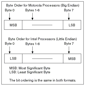
As shown in the following figure, Motorola format stores the high-order byte at the starting address, while the Intel format stores the low-order byte at the starting address. The low-order byte contains the bits for the lowest possible values (that is, 0-255), while the high-order byte contains the bits that specify the large values (that is, 256-65535 in a short integer).

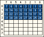
Example: Intel Format
The following figure shows the Intel format for a channel with Start Bit=0 and Number of Bits=32.

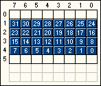
Example: Motorola Format
The following figure shows the Motorola format for a channel with Start Bit=32 and the Number of Bits=32.

 |
Note Vector's CANdb Editor supports Motorola Forward and Motorola Backward byte order. Motorola Backward is the same as Motorola Forward, except that the Start Bit counts from the last bit of the message. When you import Motorola Backward channels from a CANdb file, MAX converts the Start Bit to Motorola Forward conventions. |
Data Type
Data Type defines how the bits in the channel are interpreted. Unsigned type can represent only positive integer values, Signed type can represent positive and negative integers, and IEEE Float can represent any number with 7 or 15 significant decimals (32 or 64 bit).
Scaling Factor and Offset
You can use Scaling Factor and Offset to convert the raw data in a message to or from scaled floating-point units.
You can linearly scale the raw data in the message by using the formula y = a*x + b, where a represents the scaling factor and b the scaling offset. x is the value the channel bits represent according to the data type, and y is the resulting scaled channel value.
Scaling can change the range of values the Data Type represents.
Minimum and Maximum Value
The Maximum and Minimum values are used to set the range for the floating-point units of the channels.
The Channel API CAN Read and CAN Write functions do not coerce samples when converting to or from CAN messages.
Default Value
Default Value configures the default value of the channel in scaled floating-point units.
In the Channel API CAN Read function, the default value is returned if no message is received since the start of the application.
In the Channel API CAN Write function, default values are written for channels not specified in the task of the Initialize function.
Refer to the descriptions of the CAN Read and CAN Write functions in the NI-CAN Help at Help»Help Topics»NI-CAN»Hardware and Software Manual for further information.
Unit
Unit configures the channel unit string. The string is no more than 64 characters in length. You can use this value to display units (such as volts or RPM) along with the channel's samples.
Comment
Comment contains any comment for documentation purposes. The maximum size of the comment is 1024 characters.
Mode-dependent Channels
Mode-dependent channels are defined on the mode item. They are only valid when the mode channel in the frame has the value defined in the mode properties dialog box. Channels within the mode must not overlap each other, but it is allowed to overlap channels in another mode of the same multiplexer. For more information on mode-dependent channels, refer to Mode-dependent Channels in MAX.
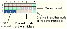
The message overview in the channel properties dialog box displays other channels coded by colors:
Orange: These bits are used by non-dependent channels or channels defined in another multiplexer. It is not allowed to overlap them with bits of the current channel.
Green: These bits are used by mode-dependent channels in the same multiplexer, but with another mode value. It is allowed to overlap those bits by the current channel bits.
Gray: Other channels in the same mode and the mode channel defined in the multiplexer dialog box are displayed with bit numbers.
