This chapter provides the following information:
 Installing
the Driver Software
 Changing
Configuration Parameters
 Installing
Broadcom Advanced Server Program
 Uninstalling
Broadcom Advanced Server Program
 Configuring
Teaming Configuring VLANs
Installing the Driver Software
The Gigabit Ethernet Adapter must be physically installed in your system prior to installing the driver software. See "Installing the Hardware" for details.
 |
NOTE A network device driver must be installed before the Gigabit Ethernet Adapter can be used with your Windows NT system. BACS Help files require Internet Explorer 5.0 or later to work properly. |
 |
NOTE We recommend using Internet Explorer 5.0 to view help files. |
Install the adapter software for Windows NT as follows:
- Verify that the Windows NT system is upgraded with
Service Pack 4 or later.
- Start your Windows NT system and log in. You must
have Network Administrator privileges to install the driver software.
- Open the Control Panel.
- In the Control Panel, double-click the Network icon.
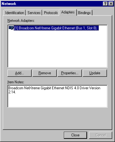
- When the Network window opens, select the Adapters
tab.
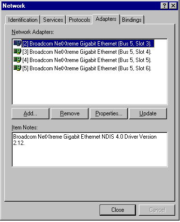
- Click Add to install a new adapter.
All previously installed drivers are listed under Network Adapters.
- When the Select Network Adapter window opens, click Have Disk....
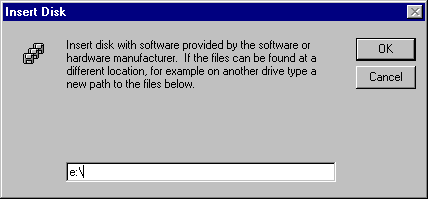
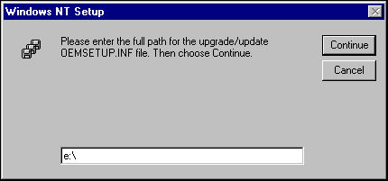
- When prompted, insert the Broadcom CD-ROM into your system's
CD-ROM drive, type the path to the driver, and click OK.
For example, to install the adapter driver software for Windows NT, type e:\ in the Insert Disk location box (where "e:" is the designation of the CD-ROM drive on your system).
 |
NOTE - If you acquired the adapter software on floppy disk or from the Broadcom support website, enter the path to where the adapter driver files reside on your system. |
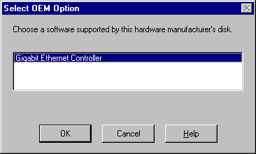
- With "Gigabit
Ethernet Controller" highlighted in
the Select OEM Option window, click OK.
The adapter files are installed, then the Network window is displayed showing the newly installed adapter.
-
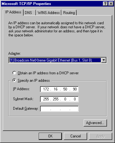
Click Close, then the Microsoft TCP/IP Properties window appears.
-
Configure the TCP/IP protocol and click OK.
- When prompted to restart your computer, click Yes.
Changing Configuration Parameters
Once the adapter driver software has been installed, you can examine and change the configuration options at any time. The following adapter parameters are user-configurable:
- Basic properties: Tx and Rx Flow Control, Duplex Mode, and Port Speed
- Optional properties: Failover Team Configuration and VLAN Configuration
Gigabit Ethernet Controller Parameters Screen
To configure adapter parameters, first bring up the Gigabit Ethernet Controller parameters screen as follows:
- Open the Control Panel and right-click the Network icon.
- When the Network window opens, select the Adapters tab.
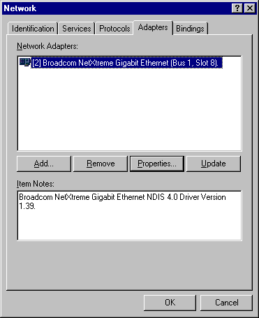
The bus and slot numbers of the highlighted adapter are listed as part of the adapter name in the Network Adapter window.
- Select the desired adapter from the Network Adapters window and click on Properties. The Gigabit Ethernet Controller parameters window opens.
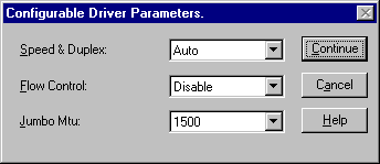
The possible adapter parameter types are:
- Speed & Duplex
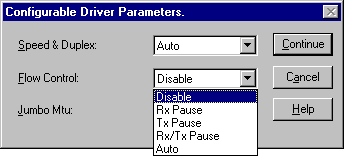
- Flow Control
- Jumbo Mtu
Refer to the parameter settings below for configuration details.
Speed & Duplex Parameter
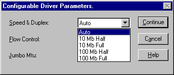
The Speed & Duplex parameter allows the user to set the connection speed duplexed to the network. Note that Duplex Mode allows the adapter to transmit and receive network data simultaneously. The adapter is set to Auto (optimum connection) by default. Set the speed and mode as described and shown below:
- Auto - (Default) Sets the speed and mode for optimum network connection (recommended)
- 10 Mb Half - Sets the speed at 10Mbps and mode to Half Duplex
- 10 Mb Full - Sets the speed at 10Mbps and mode to Full Duplex
- 100 Mb Half - Sets the speed at 100Mbps and mode to Half Duplex
- 100 Mb Full - Sets the
speed at 100Mbps and mode to Full Duplex
 |
NOTES Auto is the recommended selection. This selection allows the adapter to dynamically detect the line speed and duplex mode of the network. Whenever the network capability changes, the adapter will automatically detect and adjust to the new line speed and duplex mode. Also, when Auto is selected, the 1Gbps speed detection is enabled. |
Flow Control Parameter
The Flow Control parameter allows the user to enable or disable the receipt or transmission of PAUSE frames. PAUSE frames enable the adapter and the switch to control the transmit rate. The side that is receiving the PAUSE frame will momentarily stop transmitting. The recommended selection is Disable, which will configure the adapter to ignore PAUSE frames. Disabled by default, to enable Flow Control to receive, transmit, or receive and transmit PAUSE frames, select the appropriate parameter from the drop-down menu described and shown below.
- Disable - (default) PAUSE frame receipt and transmission is disabled (recommended)
- Rx PAUSE - PAUSE frame receipt is enabled
- Tx PAUSE - PAUSE frame transmission is enabled
- Rx/Tx PAUSE - PAUSE frame receipt and transmission is enabled
- Auto - PAUSE frame receipt and transmission is optimized
Jumbo Mtu Parameter
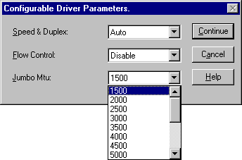
The Jumbo Mtu parameter allows the adapter to transmit and receive oversized Ethernet frames that are greater than 1514 but less than 9000 bytes in length. Note that this parameter will require a switch that is able to process large frames.
Set at 1500 bytes by default, to increase the size of the received frames, select the byte quantity in 500-byte increments from the drop-down menu shown below.
Save Settings
- When adapter parameter configuration is complete, click Continue at the Gigabit Ethernet Controller screen to accept the settings..
- When prompted to restart your computer, click Yes.

The system restarts, using the new configuration settings.
- When the system returns to proper operation, verify that the adapter port LEDs operate as described in Table 1 in the Introduction.
 |
NOTE - If no configuration changes have been made, you can click No to close the configuration session without restarting your system. |
 |
NOTE If other adapters in your system use TCP/IP bindings, the TCP/IP Properties window opens. Perform any necessary TCP/IP configuration and click OK when finished. For help in configuring TCP/IP protocol, consult your Microsoft Windows NT 4.0 documentation. |
Updating the Driver Software
Do the following to replace version 4.0 adapter driver software with newer versions as they become available.
- Start your Windows NT system and log in. You must have Network Administrator privileges to install the driver software.
- Open the Control Panel and double-click the Network icon.
- When the Network window opens, select the Adapters
tab.

Any previously installed Gigabit Ethernet driver software is listed under Network Adapters.
- Select a Broadcom Gigabit Ethernet Adapter and click Update.
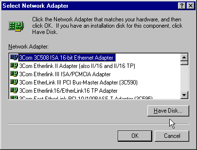
- When the Select Network Adapter window opens, click Have
Disk....
- When prompted, insert the Broadcom CD-ROM into your system's
CD-ROM drive, type the root path to the drive, and click Continue.
For example, type e:\
(Where "e:" is the designation of the CD-ROM drive on your system).
The system then copies the appropriate adapter files from the CD-ROM.
 |
NOTE - If you acquired the adapter software on floppy disk or from the Broadcom support website, enter the path to where the adapter driver files reside on your system. |
- When the copying process is complete, click Close in the Network window.
- When prompted to restart your computer, click Yes. The system restarts using the new configuration settings.
Before physically removing an adapter from your system, first remove the adapter driver software.
- Start your Windows NT system and log in. You must have Network Administrator privileges to remove the driver software.
- Open the Control Panel and double-click the Network icon.
- When the Network window opens, select the Adapters
tab.

Any previously installed Gigabit Ethernet Adapter is listed under Network Adapters.
- Individually select each Gigabit Ethernet Adapter you want to remove and click Remove.
- Once the appropriate adapters have been removed, click Close.
- When prompted to restart your computer, click Yes.
- Right click on Network Neighborhood.
- Select Properties.
- Select the Protocols tab.
- Select Add. The following
screen appears.
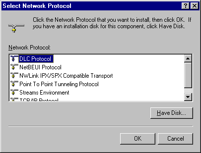
- Select Have Disk. The following
screen appears.
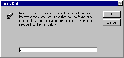
- Insert the software CD ROM and
enter the CD drive path in the dialog box. Select OK. The following
screen appears.
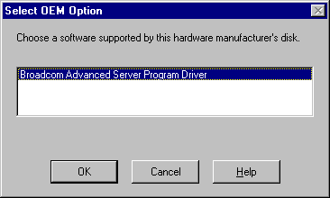
- Select OK.
- The Broadcom Advanced Server Program Driver screen appears. You can choose to configure a team, or select OK and perform the configuration procedure at a later time.
- Select OK. The Network Dialog Box appears.
- Select Close. The reboot screen appears.
- Select Yes. This completes the NT installation procedure.
- Right click on Network Neighborhood.
- Select Properties.
- Select the Protocols tab.
The following screen appears.
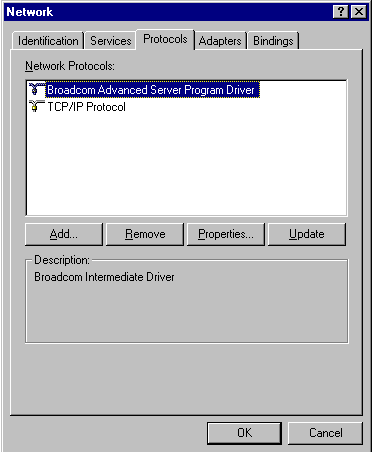
- Highlight Broadcom Advanced Server
Program Driver and click Remove. The following screen appears.
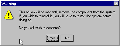
- Select Yes.
- Select Close. The following
screen appears.
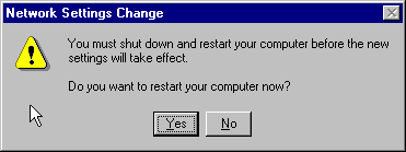
- Select Yes. This completes the uninstall procedure.
Configuring Teaming
Teaming configuration is optional. Before configuring teaming,
see the "Teaming Overview."
 |
NOTE To avoid failover problems when using BASP, make sure that the spanning tree is disabled on the switch that the network adapter is connected. |
Configuring Teaming consists of the following tasks:
- Accessing the Broadcom Advanced Server Program Driver Properties (BASP).
- Creating teams
- Adding adapters to the teams
- Assigning an IP address to the teams
- Rebooting the system
Each of these tasks is described below, along with how to delete adapters from a team and delete a team.
Accessing the BASP Driver Interface
Use this procedure to access the adapter properties for Teaming Configuration:
- Open the Control Panel and double-click the Network icon.
- When the Network window opens, select the Protocols
tab:

- Select the BASP driver and click the Properties button. The BASP window is displayed.
 |
NOTE - The BASP driver must be installed before the user can access the BASP window. Refer to "Installing Broadcom Advanced Server Program". |
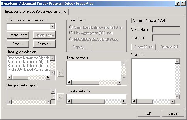
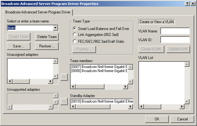
Interface components of the BASP window are described below:
- Select or enter a team name - This entry field is used to select or enter a team name.
- Unassigned adapters - This list displays all of the Ethernet adapters that are available to be added to a team. Since each adapter can be added to only one team, the adapter is removed from this list once it has been assigned to a team.
- Unsupported adapters - This list displays all unsupported adapters.
- Team Type - Smart Load Balance and Fail Over: Load balancing
FEC/GEC: Also known as general trunking. No standby adapter is allowed when this option is selected.
- Team members - This list displays all adapters that belong to a selected team.
- Standby Adapter - This list displays the standby adapter selected for a selected team.
- VLAN List - This list displays all the VLANs that have been created for the selected team.
Creating a Team and Assigning Adapters
A team is comprised of at least one primary adapter. Each adapter can belong to only one team. To configure a new team, access the Broadcom Advanced Server Program Driver Properties window and perform the following steps:
-
Enter a team name in the "Select or enter a team name" entry field.
-
Click the Create Team button.
- Place an adapter into the team.
- In the Unassigned adapters list, select the adapter(s) that you want to add to the team created in the previous step. Move the selected adapters to the Team members list box using the double arrows.
- When you are finished configuring teams, click the OK button to accept the changes.
 |
NOTE At least one adapter must be displayed in the Team Members list box. |
- If a team has no adapters assigned, you will be prompted
to add another adapter or delete the team.

-
Click the OK button. When team configuration has been correctly performed, one Virtual Team adapter driver will be created for each configured team and will appear along with the other adapters in the Network and Dial-up Connections window.
-
Configure the Team IP address if necessary. If other adapters in your system use TCP/IP bindings, the TCP/IP Properties window will open. Configure the IP address and any other necessary TCP/IP configuration for the team and click the OK button when finished.
Removing Adapters from a Team
To remove an adapter from its assigned team, select the
adapter in the Team Members list and press the Delete key or the double-left
arrow. The adapter will be removed from the team list and will reappear in the
Unassigned adapters list.
 |
NOTE If you remove an adapter from a team, you must reboot the system before the changes takes effect. |
Deleting a Team
To delete a configured team and release its assigned adapters, select the team in the team list and click Delete Team. The team and all its assigned adapters will be removed from the team list. The released adapters will reappear in the Unassigned adapters list.
 |
NOTE Adapters that are part of a team inherit all the basic configuration properties of the team, including VLANs associated with the team. If you delete a team, any VLANs configured for that team will also be deleted. |
Configuring VLANs
VLANs Configuration is optional. Before configuring VLANs,
see the "VLANs Overview."
 |
NOTE Adapters that are members of a Team can also be configured to support VLANs. However, VLANs cannot be configured for non-Broadcom adapter. |
By default, Gigabit Ethernet Adapters are configured with VLAN support disabled. Up to 64 VLANs can be defined for each team on your server. Configuring VLANs consists of the following tasks:
- Accessing the VLAN configuration interface.
- Adding VLAN(s) to the team(s). This includes assigning a unique identifier and name for each new VLAN.
- Rebooting the system.
 |
NOTE When adding 64 VLANs, the
64th VLAN must have a VLAN ID of 0 (63 VLANs are tagged and 1 VLAN is
untagged).
|
Each of these tasks is described below, along with how to delete VLANs or modify the properties of a configured VLAN.
Accessing the Adapter VLAN Configuration Interface
Use this procedure to access the adapter properties for VLAN Configuration:
- Open the system Control Panel and double-click the Network icon.
- When the Network window opens, select the Protocols
tab:

- Select the BASP driver and click the Properties button. The BASP window is displayed, from where you can configure VLANs.
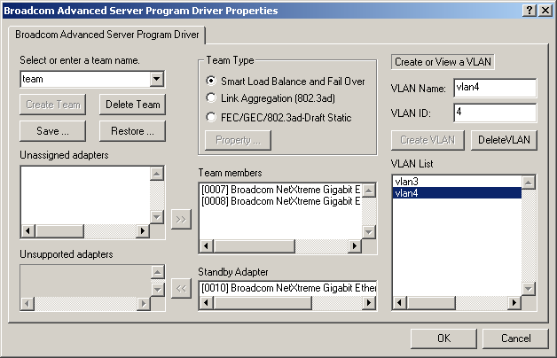
The BASP configuration window lists the installed adapters and the VLANs configured for each Team, if any. Each VLAN is identified with a unique identifier number and name that will only appear in this window. Interface components of the VLAN Configuration window are described in detail below:
- VLAN List - This list displays all of the VLANs that have been configured.
- Control Buttons - There are two control buttons: Create VLAN, and Delete VLAN. These buttons are used for creating and deleting VLANs.
Adding a VLAN
You can define up to 64 VLANs per team. To configure a new VLAN, perform the following steps:
- From the BASP window, select the team that you want to add a VLAN.
- Enter a VLAN Name and VLAN ID, the click the Create VLAN button.
- When you are finished adding VLANs to this team, click the OK button. A new virtual adapter is created for each VLAN. The TCP/IP Properties window will open. Configure the IP address and any other necessary TCP/IP configuration for this virtual adapter and click the OK button when finished.
- You must shut down and restart your computer before the new settings will
take effect. When prompted to restart your computer,
click Yes.

NOTE To maintain optimum adapter performance, your system should have 64 MB of system memory for each eight VLANs created per adapter.
Deleting a VLAN
 |
NOTE If you delete a Team, any VLANs configured for that team will also be deleted. |
To delete a configured VLAN, perform the following steps:
- From the BASP window, select the VLAN you want to delete and click the Delete VLAN button. The selected VLAN will be deleted from the VLAN list window.
- When you are finished deleting VLANs, click the OK button to accept the changes.
- You must shut down and restart your computer before the new settings will take effect. When prompted to restart your computer, click Yes.
 |
NOTE When VLANs are created and then deleted the original team name and adapter assignments [Primary\Standby] are still present, but the IP address for the team is not deleted. |
