
Troubleshooting: Broadcom NetXtreme™ Gigabit Ethernet Adapter User's Guide
This chapter provides the following information:
 Checking
if Proper Drivers are Loaded
Checking
if Proper Drivers are Loaded
Software
Problems and Solutions
Hardware Diagnostics
Loopback diagnostic tests are available for testing the adapter hardware under Windows. These tests provide access to the adapter's internal/external diagnostics, where packet information is transmitted across the physical link (refer to "Diagnostics", in the Broadcom Advanced Control Suite chapter).
The adapter has four LEDs, one for each
port speed option (10 Mbps, 100 Mbps, and 1 Gbps), and one for Activity. The
three port speed LEDs indicate active links, and the Activity LED indicates
data transfer status. Once the driver is loaded and the cables are connected
properly, the appropriate speed LED is lit and the data LED is on if data traffic
is present.
Before the port LEDs can provide troubleshooting information, the adapter must be connected to the network (see "Installing the Hardware"), and the network drivers for your particular operating system must be installed.
- Verify that the adapter driver software has been installed and that the
adapter is connected to a network.
- Check to see that the adapter status LEDs operate as described in the following table:
| LED | State | Description |
| 1000 | On | Good Gigabit Ethernet link. |
| Off | No 1000 Mbps link; possible link at different speed, possible bad cable, bad connector, or configuration mismatch. | |
| 100 | On | Good 100 Mbps Fast Ethernet link. |
| Off | No 100 Mbps link; possible link at different speed, possible bad cable, bad connector, or configuration mismatch. | |
| 10 | On | Good 10 Mbps Fast Ethernet link. |
| Off | No 10 Mbps link; possible link at different speed, possible bad cable, bad connector, or configuration mismatch. | |
| ACT | Blinking | Brief bursts of data detected on the port. |
| On | Streams of data detected on the port. | |
| Off | No data detected on the port. |
Troubleshooting Checklist
 |
WARNING Before opening the cabinet of your system for removing or inserting the adapter, please review all precautions outlined under "Safety Precautions." |
The following checklist provides recommended actions to take to resolve problems installing the Gigabit Ethernet Adapter or running it in your system.
- Inspect all cables and connections. Verify that the cable connections at the Gigabit Ethernet Adapter and the switch are attached properly. Make sure that the cable length and rating are compliant with the requirements listed in "Connecting the Network Cables."
- Check the adapter installation by reviewing "Installing the Hardware." Make sure that the adapter board is properly seated in a PCI slot. Check for specific hardware problems, such as obvious damage to board components or the PCI edge connector.
- Check the configuration settings and change them if they are in conflict with another device.
- Make sure that your system is using the latest BIOS.
- Try inserting the adapter in another slot. If the new position works, the original slot in your system may be defective.
- Replace the failed adapter with one that is known to work properly. If the second adapter works in the slot where the first one failed, the original adapter is probably defective.
- Install the adapter in another functioning system and run the tests again. If the adapter passed the tests in the new system, the original system may be defective.
- Remove all other adapters from the system and run the tests again. If the adapter passes the tests, the other adapters may be causing contention.
Checking if Proper Drivers are Loaded
The following section describes how to check if the proper drivers are loaded for Windows, NetWare, and Linux.
Windows
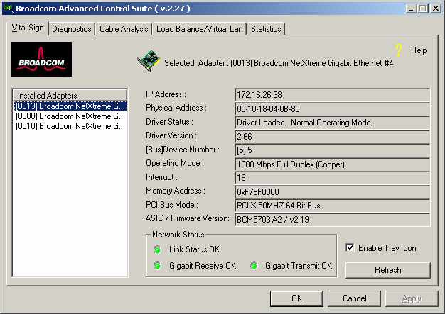
The Broadcom Advanced Control Suite, Vital Sign screen allows you to view vital adapter information, network status, and network connectivity. Active adapters are listed.
- From the Vital Sign screen, select the Broadcom adapter to be tested.
- Press Refresh to display the driver status of the selected adapter.
 |
NOTE Information for non-Broadcom adapters is less comprehensive than information listed for Broadcom adapters. |
NetWare
To verify that the driver is loaded properly, type
LOAD B57.LAN FRAME_ETHERNET_II NAME=B57_1_EII
This command automatically verifies if the link is active, and if so displays "Link is up".
From the command line, type config then press Enter. The following status information is displayed:
Broadcom NetXtreme™ Gigabit Ethernet Adapter
Version:
Hardware Setting:
Mode Address:
Frame Type:
Board Name:
Lan Protocol: ARP (see note)
LAN Protocol: IP Addr: (see note)
|
*NOTE The LAN protocol status appears after assigning an IP address to the adapter (i.e., bind). |
Linux
To verify that the bcm5700.o driver is loaded properly, run
lsmod
If
the driver is loaded, a line similar to the one below appears, where <size>
|
Module
|
Size
|
Used by
|
|
BCM5700
|
<size>
|
<n>
|
Solaris
To verify that the bcme driver is loaded properly, run
modinfo | grep bcme
A line appears showing that the driver is loaded.
Running Cable Diagnostics
The following section describes how to run the cable diagnostics from the Broadcom Advanced Control Suite. Refer to "Broadcom Advanced Control Suite," for setups and initialization.
|
NOTE This test is designed to work for a 1 gigabit copper link (1000BASE-T) only. |
Cable Analysis
From the Cable Analysis screen the user can monitor conditions of an Ethernet CAT5 cable connection within a cable plant in an Ethernet network.
|
NOTE The network connection will be lost when running these tests. |
Length
The Length sub tab allows you to verify cable length and determine whether your configuration has the appropriate cable, which are calculated by a Return Loss algorithm. This utility allows you to determine whether the problem is with the adapter or in the cable plant.
- From the Cable Analysis/Length screen, select the Broadcom adapter to be tested.
- Click Initialize, then
click Test to display the status of the selected adapter.
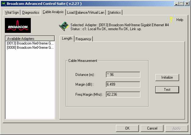
Interface components for the BACS Cable Analysis/Channel Pairs window are described below:
-
Distance: This field presents the estimated cable length in meters by averaging all four channels using Return Loss algorithms.
-
Margin: Margin yields the minimum distance between the measured cable pair and the maximum IEEE 802.3ab limits. The unit is in dB.
- Frequency Margin: This measures the minimum distance between the measured cable pair and the maximum IEEE 802.3ab limits in the frequency domain. The unit is in MHz.
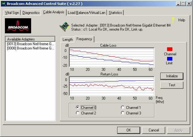
Frequency
Each channels frequency response is displayed based the computation by the cable algorithms. The two graphs represent the values calculated by the Cable Loss and Return Loss algorithms. The vertical axis represents the gain in dB and the horizontal axis represents the operating frequency. The blue graph is the IEEE 802.3ab limit and the red graph is the actual computed values for a particular twisted pair. The minimum Margin and Frequency Margin fields in the Cable Length display are derived from these graphs.
|
NOTE Network connection will be lost when running this test. |
- From the Cable Analysis/Frequency screen, select the Broadcom adapter and channel to be tested.
- Press Initialize, then
press Test to display the status of the selected adapter.
Cable Diagnostics Display
The combination of the cable length and the cable status reveal the state of the cable connection between the local adapter and the far end node (hub/switch/routers). The cable status will display possible problems associated with the cable if the cable is not in working order. In this case, displayed cable length is meaningless since the correct cable length cannot be calculated properly with a broken cable. The status window displays various error messages that diagnose possible problems associated with the cable.
Testing Network Connectivity
The following section describes how to test network connectivity for Windows, NetWare, and Linux.
Windows
Use the ping command to determine if network connectivity is working.
- Select Run from the Windows
Control Panel, this displays the Run command window.
- Type cmd (Windows 2000 and Windows .NET) or type command (Windows 98) and click OK.
- Type ipconfig /all to display
the command window.
- Type ping <IP address>
from the command line, then press Enter.
This displays the network connectivity information.
NetWare
Ping an IP host on the network to verify connection has been established:
From the command line, type ping <IP address>, then press Enter.
This will display the packet send/receive status.
Linux/SCO OpenServer/UnixWare/Solaris
To verify that the Ethernet interface is up and running, run 'ifconfig' to check the status of the Ethernet interface. 'netstat -i' can also be used to check the statistics on the Ethernet interface. Consult manual pages for more information on 'ifconfig' and 'netstat'.
Software Problems and Solutions
This section provides a list of known software problems and solutions for the operating systems below.
Windows 2000
The following table lists know problems and solutions using Windows 2000:
|
Problem: Able to create Broadcom LAC connections icons having same name under network properties menu. |
Solution: In Windows 2000, each network adapter installed properly will have an icon in Network Properties window. The name of the icon is usually in the form of "Local Area Connection ##" and where ## is a number starting from 1. The names of icon can be changed by right clicking the icon and selecting rename. The name of the icon is only meaningful to the Network Properties window. Sometimes the system administrators will rename these icons to easily differentiate the network connections. When BASP is configured, BASP will create additional adapter icons and rename the icons. The naming convention is to allow end users to quickly identify the adapter with corresponding team and VLAN. The names of the icons created by BASP therefore are not recommended to be changed. |
|
Problem: Uninstalling the BASP software and user is prompted to reboot early |
Solution: In Windows 2000, after configuring BASP team, the system may sometimes prompt user to reboot. This is because Plug and Play on W2k may fail to commit any change in the network protocol binding. Users can choose not to reboot and continue configuring intermediate driver without having any side effect. When user has finished all the configuration, it is required to reboot. |
|
Problem: Cannot enable VLAN after it is disabled |
Solution: In Windows 2000, BASP creates additional network connections in "Network Connection and Dail-up" Window. Similar to physical network connections, these virtual connections can be disabled via the context menu. However, if these virtual connections are re-enabled, the system will report error as "connection failed!". This is known problem with Windows 2000. When this happens, reboot the system will enable the virtual connection again. |
| Problem: Able to configure Internet Connection Sharing (ICS) when there aren't any unassigned adapters. | Solution: Windows 2000 networking is shipped with the Internet Connection Sharing (ICS), which is designed to allow multiple computers accessing the Internet via a Windows 2000 system. To configure ICS, a user would need to select a network connection as "outside" connection, and another network connection as "inside" connection. Broadcom has observed that ICS allow any available network connection to be "outside" and "inside" connection, regardless of the BASP team configuration. Broadcom recommends that the user not select any network connection that is part of the BASP team to be "outside" and "inside." |
|
Problem: Team configuration is not retained when user goes back to edit. |
Solution: In configuring BASP team configuration, the actual changes of the configuration is not committed until the user click "OK" in "Network Properties" window. If a user chooses not click OK and instead goes back to the BASP team configuration window, all the previous uncommitted changes will be lost and user will need to reenter the configurations. As a workaround, the user should always click "OK" in "Network Properties" window after making changes. |
|
Problem: IP address is configurable on a member of the team. |
Solution: When a team is created, the TCP/IP properties for the adapters are unselected. The user can manually select and configure TCP/IP properties of the adapters and configure an IP address. This is a limitation of the Windows 2000 network installation paradigm, where this invalid configuration is still allowed. |
|
Problem: When creating 64 VLANs, all virtual adapters show disconnected or one of the 64 VLANs show disabled. |
Solution: The maximum VLAN configurations are 63 tagged and one untagged VLAN ID 0. If 64 tagged VLANs are created, they are disconnected. A reboot is required and only 63 tagged VLANs show links, while a 64th is disabled. |
Linux
The following table lists known problems and solutions using Linux:
Linux-Basp |
|||
| Problem: When obtaining the IP for a SLB's virtual interface via DHCP, the IP-gets lost under heavy traffic. | Solution: Always set a static IP for all the virtual interfaces in a SLB team. | ||
| Problem: Make install fails on Turbo Linux 7.0 IA64. | Solution: The symbolic link under /lib/modules/<kernel-version>/build
points to an empty directory. To successfully install BASP using `make install`, re-link /lib/modules/<kernel-version>/build to point to /usr/src/<kernel-version>/. |
||
Linux-Core |
|||
| Problem: Compiling the driver fails under SuSE's 7.x. |
Solution: If compiling the driver under SuSE's 7.x distributions and errors are reported, follow the general guidelines below to rebuild the kernel source tree:
where <kernel_version>
is the actual kernel version used in the SuSE distribution.
|
||
| Problem: Zero copy performance is low on Red Hat 7.1. |
Solution: Red
Hat 7.1 loads the ipchains module by default. IPCHAINS is not Example:
|
||
Broadcom Boot Agent
The following table lists known Broadcom Boot Agent problems and solutions:
| Problem: Unable to obtain network settings through DHCP using PXE. |
Solution: For proper operation make sure that the STP (spanning tree protocol) is disabled or portfast mode (for Cisco) is enabled on the port to which the PXE client is connected. For instance, set spantree portfast 4/12 enable. |
||
Broadcom Advanced Server Program (BASP)
The following table lists known BASP problems and solutions:
| Problem:
802.3ad team member links disconnect and reconnect continuously. |
Solution: This is a
3rd party issue. It is seen only when configuring an 802.3ad team This does not occur with a Cisco Catalyst 6500. |
||
UnixWare
The following table lists known UnixWare problems and solutions:
| Problem:
In some instances with a Broadcom LOM, when you try to add the LAN adapter,
multiple devices may show up. |
Solution: Login as root
and run "/sbin/resmgr |more" You should see the following:
|
||
Miscellaneous
The following table lists known miscellaneous problems and solutions:
| Problem: When the bus on the system is operating at PCI mode, Broadcom NetXtreme Gigabit Ethernet will perform at PCI mode if it is added by Hot Plug. | Solution: When the system is booted up without any adapter, the bus will operate at the lowest mode which is PCI. This problem can be overcome by rebooting the system. | ||
| Problem: The Broadcom NetXtreme Gigabit Ethernet adapter may not perform at optimal level when it is added by Hot Plug on some system. | Solution: This is because the system BIOS in some system does not set the cache line size and the latency timer, after the adapter is added by Hot Plug. This problem can be overcome by rebooting the system. | ||
| Problem: The Broadcom NetXtreme Gigabit Ethernet adapter can not be seen on the PCI BUS. | Solution: This is because some of the older servers are advertising themselves as PCI-X capable systems. This causes the NetXtreme network adapter to operate in PCI-X mode; therefore; not to be seen by the PCI bus. This problem can be overcome by configuring the firmware to operate in forced pci mode. Refere to b57diag for configuration instructions. | ||