Your Sound Blaster X-Fi I/O Drive*
The X-Fi I/O Drive provides additional connectivity for a number of other devices.
Front panel
| |
Jack or Connector
|
Description
|
|
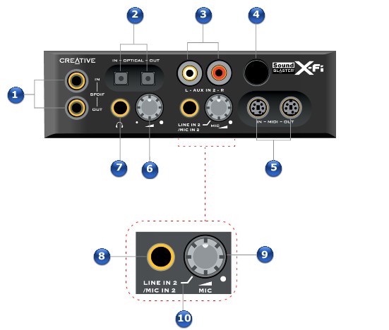
1.
|
Coaxial SPDIF In/Out jacks
|
Connect digital audio recording/playback devices with coaxial jacks (for example, MiniDisc recorders, Digital Audio Tape recorders or external hard disk recorders) to these jacks.
|
|
2.
|
Optical SPDIF In/Out jacks
|
Connect recording/playback devices with optical jacks (for example, MiniDisc recorders, Digital Audio Tape recorders or external hard disk recorders) to these jacks.
|
|
3.
|
Auxiliary 2 Line In jacks
|
Connect one end of an RCA cable to these jacks. Connect the other end to the RCA outputs on analog devices like VCRs, TVs and CD players.
|
|
4.
|
Infrared receiver
|
Receives infrared signals from the remote control* and transmits them to your computer.
|
|
5.
|
Mini MIDI In/Out connectors
|
Connect MIDI devices to these connectors using mini-MIDI-to-standard-MIDI adapter cables*.
|
|
6.
|
Headphone volume dial
|
Controls the volume to your headphones. Turn clockwise to increase the volume, and counterclockwise to decrease the volume.
|
|
7.
|
Headphone jack
|
Connect stereo headphones with a 6.35 mm (1/4-inch) stereo plug to this jack. Speaker output will be muted if the Automatically mute speakers check box is selected in Audio Console or Entertainment Mode. For more information, refer to their online Help.
|
|
8.
|
Line In 2/Mic In 2 jack
|
Connect a line-level source (for example, a cassette player or an electric guitar running through a Pre-amp FX Box) or a microphone to this jack.
|
|
9.
|
Line In 2/Mic In 2 dial
|
Selects Line In 2 or Mic In 2. Also controls the input gain. Turn the dial clockwise to increase the input gain, and counterclockwise to decrease the input gain.
|
|
10.
|
Line In 2/Mic In 2 separator mark
|
To select Line In 2 for line-level sources, turn the dial counterclockwise over the Line In 2/Mic In 2 separator mark until you hear a "click". To select Mic In 2, turn the dial clockwise over the separator mark until you hear a "click".
|
Top panel
| |
Jack or Connector
|
Description
|
|
1.
|
Jumper JP1
|
Connect the shunt supplied with your X-Fi I/O Drive to this jumper if you want to use a dynamic microphone. Do not connect the shunt if you want to use a condenser microphone or computer microphone.
|
|
2.
|
Power connector
|
Connect the power splitter cable supplied with your X-Fi I/O Drive to this connector.
|
|
3.
|
AD_EXT connector
|
Connect one end of the AD_EXT cable to this connector. Connect the other end to the AD_Link connector on the Sound Blaster X-Fi audio card.
|
Notes
- *Available with some models of your audio device, or as an upgrade accessory in some regions.


