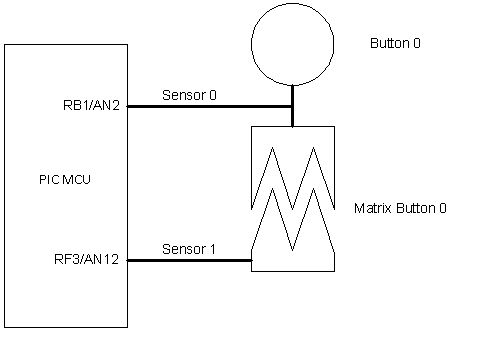
Let’s consider an application example for the following hardware configuration:

In the system there are 2 sensors, 1 button and 1 matrix button. Thus in mTouchConfig.h MTOUCH_SENSORS_NUMBER must be set to 2, MTOUCH_BUTTONS_NUMBER and MTOUCH_MATRIXBUTTONS_NUMBER must be set to 1. All IOs connected to sensors must be set as ANALOG in the application (see PCFGx, ANSx or ANSELx registers description in PIC Microcontroller datasheet ).
The program should be started from MTouchInit(…) function call to initialize the mTouch Library. Then for each sensor in the system the sensors parameters must be set with MTouchSetSensor(…) function calls. From this point the mTouch library has all information about sensors and the application can get samples from them by calling MTouchAcquisition(…) function periodically. It can be done with a timer interrupt.
All controls in the application also must be initialized. In this example we have button and matrix button. Functions MTouchSetButton(…) and MTouchSetMatrixButton(…)assign sensors for these controls and define decoding methods. To get states of controls the MTouchDecode() must be run periodically. For this example the application code can be:
// Header file for mTouch library API.
#include "mTouch.h"
void main(void)
{
.......................................................
// STEP 1
// mTouch library initialization.
MTouchInit();
// STEP 2
// Sensors initialization. All sensors must be initialized
// see MTOUCH_SENSORS_NUMBER in mTouchConfig.h).
// PLEASE READ "SENSOR OPTIMIZATION (DEBUG MODULE)" CHAPTER
// TO SELECT OPTIMAL PARAMETERS.
// Sensor #0 is connected to RB1/AN2 pin
MTouchSetSensor(0, // sensor number
&TRISB, // port B
&LATB,
1, // IO bit number
2, // analog channel number
-1, // press detection threshold by default
// (see MTOUCH_DEFAULT_THRESHOLD in mTouchConfig.h)
-1, // oversampling by default
//(see MTOUCH_DEFAULT_OVERSAMPLING in mTouchConfig.h)
-1 ); // CTMU charge delay by default
//(see MTOUCH_DEFAULT_CHARGE_DELAY in mTouchConfig.h,
// not used for CVD acquisition)
// Sensor #1 is connected to RF3/AN12 pin
MTouchSetSensor(1, // sensor number
&TRISF, // port F
&LATF,
3, // IO bit number
12, // analog channel number
-1, // press detection threshold by default
// (see MTOUCH_DEFAULT_THRESHOLD in mTouchConfig.h)
-1, // oversampling by default
//(see MTOUCH_DEFAULT_OVERSAMPLING in mTouchConfig.h)
-1 ); // CTMU charge delay by default
//(see MTOUCH_DEFAULT_CHARGE_DELAY in mTouchConfig.h,
// not used for CVD acquisition)
// STEP 3
// Buttons initialization. All buttons must be initialized
//(see MTOUCH_BUTTONS_NUMBER and MTOUCH_MATRIXBUTTONS_NUMBER in
// mTouchConfig.h).
// The button #0 is connected to sensor # 0
MTouchSetButton(0, // button number
0, // sensor number
DECODE_TOGGLE); // decode method
// The matrix button #0 is connected to sensor # 0 and sensor # 1
MTouchSetMatrixButton(0, // button number
0, // first sensor number
1, // second sensor number
DECODE_PRESS_RELEASE); // decode method
// STEP 4
// Timer interrupt initialization to call mTouchAcquisition(...)
// pereodically.
TimerInterruptInitialization();
while(1)
{
// STEP 4
// Decode all controls periodically.
MTouchDecode();
// STEP 5
// Get current states of the buttons.
Led_ALLOff();
// button #0
if(MTouchGetButtonState(0) == CONTROL_PRESSED) { Led0On(); }
// matrix button #0
if(MTouchGetMatrixButtonState(0) == CONTROL_PRESSED) { Led1On(); }
}
}
// Timer interrupt service routine.
void __attribute__((interrupt, shadow, auto_psv)) _T4Interrupt(void)
{
// STEP 6
// Scan sensors periodically.
MTouchAcquisition();
// Clear timer interrupt flag.
TMR4 = 0; IFS1bits.T4IF = 0;
}.