|
TIMER
|
Usage
This example demonstrates the generation of events for the defined time intervals using TIMER APP considering CCU4 HW timer module. Initially the APP is configured to generate the events for every one second. And after getting the 10 events(10 seconds), time interval is updated in ISR with 0.5 second.
Generation of events is indicated by toggling an LED.
Instantiate the required APPs
Drag an instance of TIMER, INTERRUPT and DIGITAL_IO APPs. Update the fields in the GUI of these APPs with the following configuration.
Configure the APPs
TIMER APP:

-
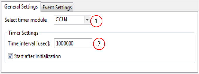
Select CCU4 module
Note: If all the timers in the CCU4 module are consumed, manually switch one of the existing instances of APPs to CCU8 and try again. -
Set the time interval to 1sec
Time interval [usec]: 1000000
DIGITAL_IO APP:

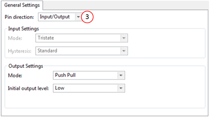
- Set pin direction to output by choosing - Pin direction : Input/Output
INTERRUPT APP:

-
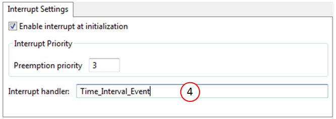
Enter an appropriate ISR handle name for the Time interval event.
e.g. Time_Interval_Event
Note : This ISR shall be defined by user application (main.c)
Signal Connection
Establish a HW signal connection between the TIMER and the INTERRUPT APP to ensure TIMER events goes to INTERRUPT.

- Connect TIMER_0/event_time_interval -> INTERRUPT_0/sr_irq to ensure assigning ISR node to the time_interval event.
Manual pin allocation

-
Select the pin to be toggled (on-board LED)
Note:The pin number is specific to the development board chosen to run this example. The pin shown in the image above may not be available on every XMC boot kit. Ensure that a proper pin is selected according to the board.
Generate code
Files are generated here: `<project_name>/Dave/Generated/' (`project_name' is the name chosen by the user during project creation). APP instance definitions and APIs are generated only after code generation.
-
Note: Code must be explicitly generated for every change in the GUI configuration.
Important: Any manual modification to APP specific files will be overwritten by a subsequent code generation operation.
Sample Application (main.c)
 #include <DAVE.h>

 uint32_t event_count;

 int main(void)
 {
   DAVE_STATUS_t status;

   status = DAVE_Init();
   if (status == DAVE_STATUS_FAILURE)
   {
     XMC_DEBUG(("DAVE Apps initialization failed with status %d\n", status));
     while (1U)
     {
     }
   }

   while (1U)
   {
   }

   return 1;
 }

  //
  // User defined ISR time interval event
  // Toggles GPIO on each time tick:
  // Initial time interval: 1 second. Update time
  // Interval to 0.5 seconds after 10 seconds.
  //
 void Time_Interval_Event(void)
 {
   /* Acknowledge Period Match interrupt generated on TIMER_CCU_1 */
   TIMER_ClearEvent(&TIMER_0);
   DIGITAL_IO_ToggleOutput(&DIGITAL_IO_0);

   //
   // Increment event count and update time interval to 0.5
   // seconds after 10 seconds
   //
   event_count++;
   if (event_count == 10U)
   {
     if(TIMER_Stop(&TIMER_0) == 0U)
     {
       TIMER_SetTimeInterval(&TIMER_0, 50000000U);
       TIMER_Start(&TIMER_0);
     }
   }
 }
Build and Run the Project
Observation
- For the first 10 seconds LED is toggled for every second, and then for every 0.5 seconds.