Device Range
Device range refers to the minimum and maximum analog signal levels that the ADC can digitize. Many measurement devices can select from several ranges by changing from unipolar mode to bipolar mode or by selecting from multiple gains, allowing the ADC to take full advantage of its resolution to digitize the signal.
Unipolar and Bipolar Modes
Unipolar mode means that a device only supports a range of 0 V to +X V. Bipolar mode means that a device supports a range of -X V to +X V. Some devices support only one mode or the other, while other devices can change from unipolar mode to bipolar mode.
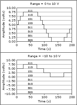
Devices that can change from unipolar to bipolar mode are able to select the mode that best fits the signal to measure. The first chart of the following figure illustrates unipolar mode for a 3-bit ADC. The ADC has eight digital divisions in the range from 0 to 10 V. In bipolar mode, the range is -10.00 to 10.00 V, as shown in the second chart. The same ADC now separates a 20 V range into eight divisions. The smallest detectable difference in voltage increases from 1.25 to 2.50 V, and you now have a much less accurate representation of the signal. The device selects the best mode available based on the input limits you specify when you create a virtual channel.

Gain Adjustment
If a device has multiple gains, it multiplies an input signal by one of the gains to make the signal take up more of the full device range. This essentially gives the device multiple ranges it can select from. For example, a device with an overall range of -10 V to 10 V and possible gains of 1, 2, and 4 can select between ranges of -10 V to 10 V, -5 V to 5 V, and -2.5 V to 2.5 V. The device selects the best gain available according to the input limits you specify when you create a virtual channel.
 |
Note Gain works differently for DSA devices. |