Bridge Configurations
This topic explains some common bridge configurations used in strain measurements.
- Quarter-Bridge Type I
- Quarter-Bridge Type II
- Half-Bridge Type I
- Half-Bridge Type II
- Full-Bridge Type I
- Full-Bridge Type II
- Full-Bridge Type III
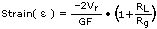
NI-DAQmx strain virtual channels use the following equation to scale voltage readings to strain units.
Vr = (VCH / VEX)STRAINED – (VCH / VEX)UNSTRAINED
where VEX is the excitation voltage, and VCH is the measured voltage.
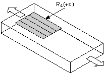
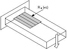
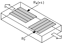
Quarter-Bridge Type I
The following figure shows how to position a strain gage resistor in an axial configuration for the quarter-bridge type I.
The following figure shows how to position a strain gage resistor in a bending configuration for the quarter-bridge type I.
Quarter-bridge type I strain gage configurations have the following characteristics:
- A single active strain gage element mounted in the principle direction of axial or bending strain.
- A passive quarter-bridge completion resistor, known as a dummy resistor, in addition to half-bridge completion.
- Temperature variation decreasing the accuracy of the measurements.
- Sensitivity at 1000 µε is ~ 0.5 mVout / VEX input.
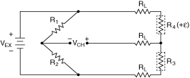
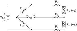
Quarter-Bridge Type I Circuit Diagram
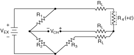
The following symbols apply to the circuit diagram:
- R1 is the half-bridge completion resistor.
- R2 is the half-bridge completion resistor.
- R3 is the quarter-bridge completion resistor, known as a dummy resistor.
- R4 is the active strain gage element measuring tensile strain (+ε).
- VEX is the excitation voltage.
- RL is the lead resistance.
- VCH is the measured voltage.
To convert voltage readings to strain units for quarter-bridge configurations, use the following equation.
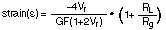
where Vr is the voltage ratio that virtual channels use in the voltage-to-strain conversion equation, GF is the gage factor, RL is the lead resistance, and Rg is the nominal gage resistance.
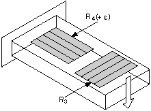
Quarter-Bridge Type II
The following figure shows how to position a strain gage resistor in an axial configuration for the quarter-bridge type II.
The following figure shows how to position a strain gage resistor in a bending configuration for the quarter-bridge type II.
Quarter-bridge type II strain gage configurations have the following characteristics:
- One active strain gage element and one passive, temperature-sensing quarter-bridge element, known as a dummy resistor. The active element is mounted in the direction of axial or bending strain. The dummy gage is mounted in close thermal contact with the strain specimen but is not bonded to the specimen, and is usually mounted transverse, or perpendicular, to the principle axis of strain. This configuration is often confused with the half-bridge type I configuration, but in the half-bridge type I configuration, the R3 element is active and bonded to the strain specimen to measure the effect of Poisson's ratio.
- Completion resistors which provide half-bridge completion.
- Compensation for temperature.
- Sensitivity at 1000 µε is ~ 0.5 mVout/ VEX input.
Quarter-Bridge Type II Circuit Diagram
The following symbols apply to the circuit diagram:
- R1 is the half-bridge completion resistor.
- R2 is the half-bridge completion resistor.
- R3 is the quarter-bridge temperature sensing element, known as a dummy resistor.
- R4 is the active strain gage element measuring tensile strain (+ε).
- VEX is the excitation voltage.
- RL is the lead resistance.
- VCH is the measured voltage.
To convert voltage readings to strain units for quarter-bridge configurations, use the following equation.
where Vr is the voltage ratio that virtual channels use in the voltage-to-strain conversion equation, GF is the gage factor, RL is the lead resistance, and Rg is the nominal gage resistance.
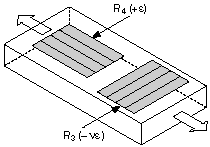
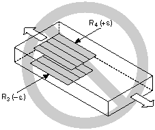
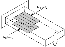
Half-Bridge Type I
The following figure shows how to position strain gage resistors in an axial configuration for the half-bridge type I.
The following figure shows how to position strain gage resistors in a bending configuration for the half-bridge type I.
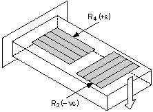
Half-bridge type I strain gage configurations have the following characteristics:
- Two active strain gage elements, one mounted in the direction of axial strain and the other acting as a Poisson gage and mounted transverse, or perpendicular, to the principal axis of strain.
- Completion resistors which provide half-bridge completion.
- Sensitivity to both axial and bending strain.
- Compensation for temperature.
- Compensation for the aggregate effect on the principle strain measurement due to the Poisson's ratio of the material.
- Sensitivity at 1000 µε is ~ 0.65 mVout/ VEX input.
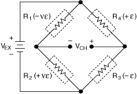
Half-Bridge Type I Circuit Diagram
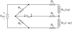
The following symbols apply to the circuit diagram:
- R1 is the half-bridge completion resistor.
- R2 is the half-bridge completion resistor.
- R3 is the active strain gage element measuring compression due to the Poisson effect (–ε).
- R4 is the active strain gage element measuring tensile strain (+ε).
- VEX is the excitation voltage.
- RL is the lead resistance.
- VCH is the measured voltage.
To convert voltage readings to strain units, use the following equation.
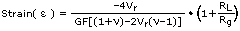
where Vr is the voltage ratio that virtual channels use in the voltage-to-strain conversion equation, GF is the gage factor, v is the Poisson's ratio, RL is the lead resistance, and Rg is the nominal gage resistance.
Half-Bridge Type II
The half-bridge type II configuration only measures bending strain.
The following figure shows how to position strain gage resistors in a bending configuration for the half-bridge type II.
Half-bridge type II strain gage configurations have the following characteristics:
- Two active strain gage elements, one mounted in the direction of axial strain on the top side of the strain specimen and the other mounted in the direction of axial strain on the bottom side.
- Completion resistors which provide half-bridge completion.
- Sensitivity to bending strain.
- Rejection of axial strain.
- Compensation for temperature.
- Sensitivity at 1000 µε is ~ 1 mVout / VEX input.
Half-Bridge Type II Circuit Diagram
The following symbols apply to the circuit diagram:
- R1 is the half-bridge completion resistor.
- R2 is the half-bridge completion resistor.
- R3 is the active strain gage element measuring compressive strain (–ε).
- R4 is the active strain gage resistor measuring tensile strain (+ε).
- VEX is the excitation voltage.
- RL is the lead resistance.
- VCH is the measured voltage.
To convert voltage readings to strain units, use the following equation.
where Vr is the voltage ratio that virtual channels use in the voltage-to-strain conversion equation, GF is the gage factor, RL is the lead resistance, and Rg is the nominal gage resistance.
Full-Bridge Type I
The full-bridge type I configuration only measures the bending strain.
The following figure shows how to position strain gage resistors in a bending configuration for the full-bridge type I.
Full-bridge type I strain gage configurations have the following characteristics:
- Four active strain gage elements, two mounted in the direction of bending strain on the top side of the strain specimen and the other two mounted in the direction of bending strain on the bottom side.
- High sensitivity to bending strain.
- Rejection of axial strain.
- Compensation for temperature.
- Compensation for lead resistance.
- Sensitivity at 1000 µε is ~ 2.0 mVout / VEX input.
Full-Bridge Type I Circuit Diagram
The following symbols apply to the circuit diagram:
- R1 is the active strain gage element measuring compressive strain (–ε).
- R2 is the active strain gage element measuring tensile strain (+ε).
- R3 is the active strain gage element measuring compressive strain (–ε).
- R4 is the active strain gage element measuring tensile strain (+ε).
- VEX is the excitation voltage.
- RL is the lead resistance.
- VCH is the measured voltage.
To convert voltage readings to strain units use the following equation.

where Vr is the voltage ratio that virtual channels use in the voltage-to-strain conversion equation, and GF is the gage factor.
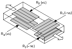
Full-Bridge Type II
The full-bridge type II configuration only measures bending strain.
The following figure shows how to position strain gage elements in a bending configuration for the full-bridge type II.
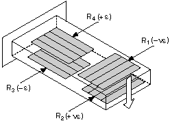
Full-bridge type II strain gage configurations have the following characteristics:
- Four active strain gage elements. Two are mounted in the direction of bending strain with one on the top side of the strain specimen and the other on the bottom side. The other two act together as a Poisson gage and are mounted transverse, or perpendicular, to the principal axis of strain with one on the top side of the strain specimen and the other on the bottom side.
- Rejection of axial strain.
- Compensation for temperature.
- Compensation for the aggregate effect on the principle strain measurement due to the Poisson's ratio of the material.
- Compensation for lead resistance.
- Sensitivity at 1000 µε is ~ 1.3 mVout / VEX input.
Full-Bridge Type II Circuit Diagram
The following symbols apply to the circuit diagram:
- R1 is the active strain gage element measuring compressive Poisson effect (–ε).
- R2 is the active strain gage element measuring tensile Poisson effect (+ε).
- R3 is the active strain gage element measuring compressive strain (–ε).
- R4 is the active strain gage element measuring tensile strain (+ε).
- VEX is the excitation voltage.
- RL is the lead resistance.
- VCH is the measured voltage.
To convert voltage readings to strain units, use the following equation.
where Vr is the voltage ratio that virtual channels use in the voltage-to-strain conversion equation, GF is the gage factor, and v is the Poisson's ratio.
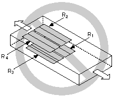
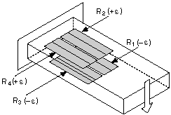
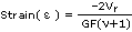
Full-Bridge Type III
The following figure shows how to position strain gage resistors in an axial configuration for the full-bridge type III.
The full-bridge type III configuration only measures the axial configuration.
Full-bridge type III strain gage configurations have the following characteristics:
- Four active strain gage elements. Two are mounted in the direction of axial strain with one on the top side of the strain specimen and the other on the bottom side. The other two act together as a Poisson gage and are mounted transverse, or perpendicular, to the principal axis of strain with one on the top side of the strain specimen and the other on the bottom side.
- Compensation for temperature.
- Rejection of bending strain.
- Compensation for the aggregate effect on the principle strain measurement due to the Poisson's ratio of the material.
- Compensation for lead resistance.
- Sensitivity at 1000 µε is ~ 1.3 mVout / VEX input.
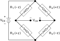
Full-Bridge Type III Circuit Diagram
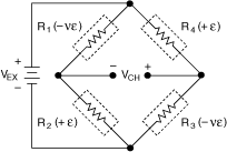
The following symbols apply to the circuit diagram:
- R1 is the active strain gage element measuring compressive Poisson effect (–ε).
- R2 is the active strain gage element measuring tensile strain (+ε).
- R3 is the active strain gage element measuring compressive Poisson effect (–ε).
- R4 is the active strain gage element measuring the tensile strain (+ε).
- VEX is the excitation voltage.
- RL is the lead resistance.
- VCH is the measured voltage.
To convert voltage readings to strain units, use the following equation.
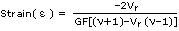
where Vr is the voltage ratio that virtual channels use in the voltage-to-strain conversion equation, GF is the gage factor, and v is the Poisson's ratio.