|
ADC_MEASUREMENT_ADV
|
Usage
The following examples demonstrate some of the use cases of the ADC_MEASUREMENT_ADV APP.
- Example to illustrate the autoscan mode (Software start continuous mode).
- Example to illustrate the software triggered conversions (Software start single shot mode).
- Example to illustrate the hardware triggered conversions (Hardware trigger single shot mode).
- Example to illustrate synchronous conversions.
Use case 1: The use case illustrates the use of the "autoscan mode" (continuous conversion). An API call starts the conversion round. After one conversion round (2 Channels) the round is automatically repeated. Hence no additional start of the conversion round is necessary. The result is cautiously read in the main loop.
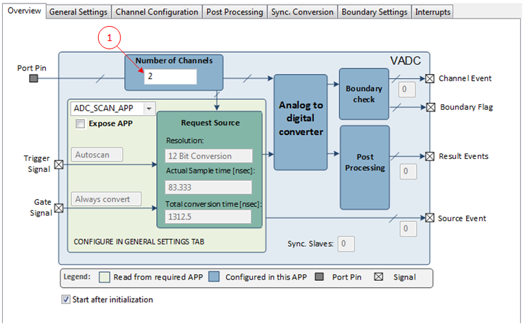
In this example the "ADC_SCAN_APP" is used. See following configuration.
Note: The conversion result is read continuously and it is independent of ADC result being ready.
The use case can also be handled with "ADC_QUEUE_APP" by disabling all "Wait for trigger" in the "Sequence Plan" tab.
Note: This configuration will immediately start the conversion after the ADC start (GUI checkbox "Start after initialization" or API for start ADC). This use case is not shown in this example.
Instantiate the required APPs
Drag an instance of ADC_MEASUREMENT_ADV APP. Update the fields in the GUI of the APP with the following configuration.
Configure the APP:
ADC_MEASUREMENT_ADV_0 APP:
- Set the number of channels to 2 .
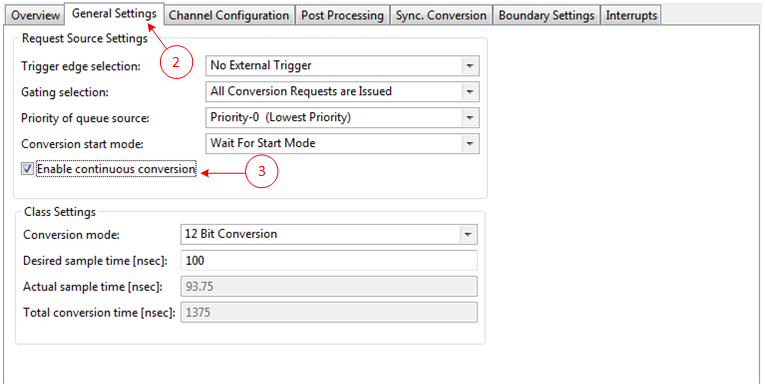
- Goto General settings Tab.
- Check the "Enable continuous Conversion" check box.
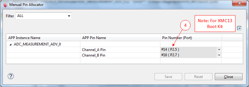
Manual pin allocation
-
Select the potentiometer Pin present in the boot kit and also another pin in available for the select board.
Note:The pin number is specific to the development board chosen to run this example. The pin shown in the image above may not be available on every XMC boot kit. Ensure that a proper pin is selected according to the board.
Generate code
Files are generated here: '<project_name>/Dave/Generated/' ('project_name' is the name chosen by the user during project creation). APP instance definitions and APIs are generated only after code generation.
-
Note: Code must be explicitly generated for every change in the GUI configuration.
Important: Any manual modification to the APP specific generated files will be overwritten by a subsequent code generation operation.
Sample Application (main.c)
 #include <DAVE.h>                 //Declarations from DAVE Code Generation (includes SFR declaration)


 int main(void)
 {
   DAVE_STATUS_t status;
   uint16_t resultA, resultB;

   status = DAVE_Init();           /* Initialization of DAVE APPs  */

   if(status == DAVE_STATUS_FAILURE)
   {
     /* Placeholder for error handler code. The while loop below can be replaced with an user error handler. */
     XMC_DEBUG("DAVE APPs initialization failed\n");

     while(1U)
     {

     }
   }

   // One Software trigger to start the conversion of the 2 channels.
   // After each conversion round(i.e after 2 channels) the conversion will be automatically repeated.
   ADC_MEASUREMENT_ADV_SoftwareTrigger(&ADC_MEASUREMENT_ADV_0);
   while(1U)
   {
     //continuously read the result value.
     //NOTE: The result read doesn't wait for the new result to be ready.
     resultA = ADC_MEASUREMENT_ADV_GetResult(&ADC_MEASUREMENT_ADV_0_Channel_A);
     resultB = ADC_MEASUREMENT_ADV_GetResult(&ADC_MEASUREMENT_ADV_0_Channel_B);
     XMC_UNUSED_ARG(resultA);
     XMC_UNUSED_ARG(resultB);
   }
 }
Build and Run the Project
Observation
The measurement is started with the ADC_MEASUREMENT_ADV_SoftwareTrigger() API call. The conversion results are read continuously and stored in "resultA" and "resultB" variable.
Use case 2:
The use case illustrates the software triggered conversions. In this use case a sequence of 2 ADC Channels will be converted. The conversion round is started with an API. After one conversion round (2 Channels) the conversion is stopped and waits for the next software start. After each conversion round a result event is generated and the ADC results are read in the ISR. After the results have been read, a new conversion is started with an API call.
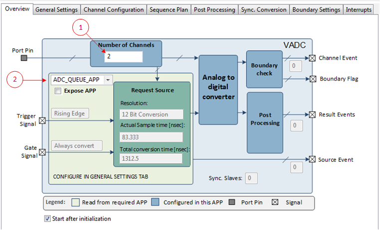
In this example the "ADC_QUEUE_APP" is used. See following configuration.
The use case can also be handled with "ADC_SCAN_APP". This use case is not shown in this example.
Note: This usecase uses an INTERRUPT APP for the result events. For those configurations refer to INTERRUPT APP help.
Note: In "ADC_SCAN_APP" the conversion sequence depends on the channels consumed. If Channel_A consumes a lower channel number than Channel_B then Channel_B would be converted first. Hence care needs to be taken when a similar setup is done while using ADC_SCAN_APP.
Instantiate the required APPs
Drag an instance of ADC_MEASUREMENT_ADV APP and one instance of INTERRUPT APP. Update the fields in the GUI of the APP with the following configuration.
Configure the APP:
ADC_MEASUREMENT_ADV_0 APP:
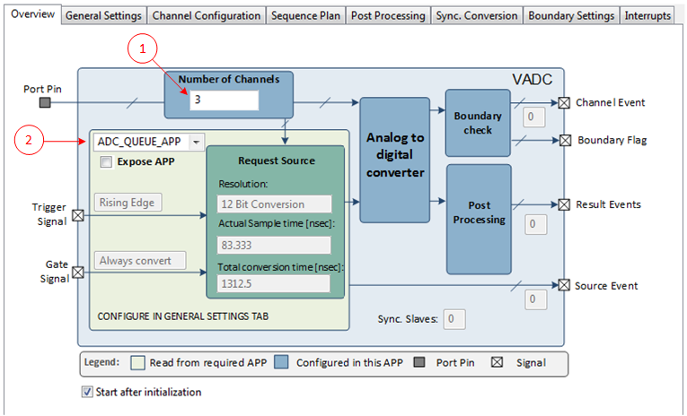
- Set the number of channels to 2 .
- Select the request source as ADC_QUEUE_APP .
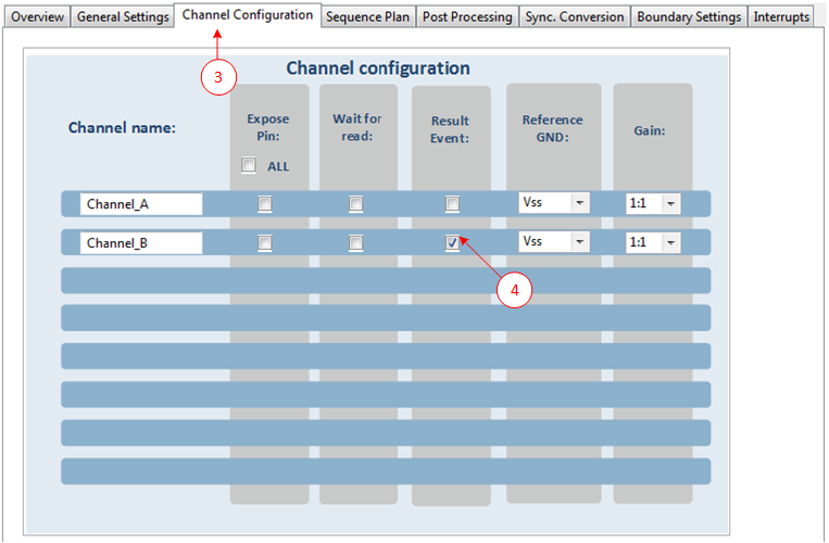
- Goto Channel configuration Tab.
- Enable the result event for Channel_B.
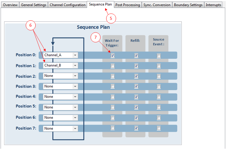
- Goto Sequence Plan Tab.
- Select the Queue Position-0 as Channel-A, Position-1 as Channel_B.
- Select "Wait for Trigger" for Channel-A.
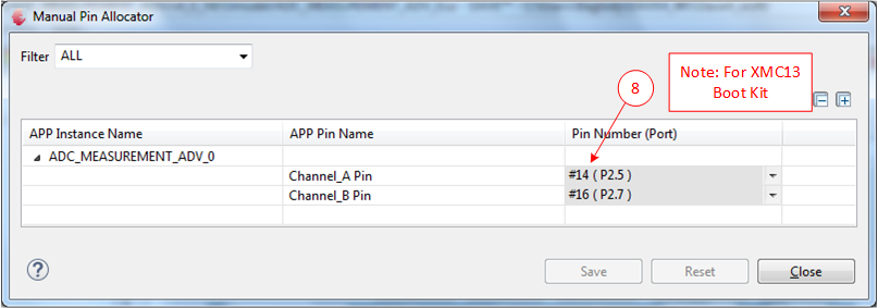
Manual pin allocation
-
Select the potentiometer Pin present in the boot kit and also another pin in available for the select board.
Note:The pin number is specific to the development board chosen to run this example. The pin shown in the image above may not be available on every XMC boot kit. Ensure that a proper pin is selected according to the board.
HW Signal Connections
- Connect the ADC_MEASUREMENT_ADV_0 event_res_Channel_B signal to INTERRUPT_0 sr_irq

Generate code
Files are generated here: '<project_name>/Dave/Generated/' ('project_name' is the name chosen by the user during project creation). APP instance definitions and APIs are generated only after code generation.
-
Note: Code must be explicitly generated for every change in the GUI configuration.
Important: Any manual modification to the APP specific generated files will be overwritten by a subsequent code generation operation.
Sample Application (main.c)
 #include <DAVE.h>                 //Declarations from DAVE Code Generation (includes SFR declaration)

 uint16_t resultA,resultB;

 // Result event for Channel_B
 void UserIRQHandler(void)
 {
       // read the results of the conversion
       resultA = ADC_MEASUREMENT_ADV_GetResult(&ADC_MEASUREMENT_ADV_0_Channel_A);
       resultB = ADC_MEASUREMENT_ADV_GetResult(&ADC_MEASUREMENT_ADV_0_Channel_B);

       //Start the next round of conversion
       ADC_MEASUREMENT_ADV_SoftwareTrigger(&ADC_MEASUREMENT_ADV_0);
 }

 int main(void)
 {
   DAVE_STATUS_t status;

   status = DAVE_Init();           /* Initialization of DAVE APPs  */


   if(status == DAVE_STATUS_FAILURE)
   {
     /* Placeholder for error handler code. The while loop below can be replaced with an user error handler. */
     XMC_DEBUG("DAVE APPs initialization failed\n");

     while(1U)
     {

     }
   }

   // One Software trigger to start the conversion of the 2 channels.
   ADC_MEASUREMENT_ADV_SoftwareTrigger(&ADC_MEASUREMENT_ADV_0);
   while(1U)
   {

   }
 }
Build and Run the Project
Observation
The measurement is started with the ADC_MEASUREMENT_ADV_SoftwareTrigger() API call. After Channel_B is converted an event is triggered and executes the ISR UserIRQHandler(). In this ISR the results of Channel_A and Channel_B are stored in "resultA" and "resultB" variables. The API call ADC_MEASUREMENT_ADV_SoftwareTrigger(&ADC_MEASUREMENT_ADV_0) in the ISR starts a new conversion round.
Use case 3:
The use case illustrates hardware triggered conversions. A hardware trigger starts the conversion round of 3 Channels. When the conversion round is finished a source interrupt is executed. In the ISR the results are read. The ADC waits now for a new hardware trigger.
In this example the "ADC_QUEUE_APP" is used, this allows a user defined sequence. See following configuration.
The use case can also be handled with "ADC_SCAN_APP". In that case it is mandatory to disable the "autoscan mode". Also the "result event" can be used to read the ADC results. Both the use cases are not handled in this example.
Note: The 10kHz hardware trigger is generated with a PWM APP.For PWM configuration refer to the PWM APP help.
Instantiate the required APPs
Drag an instance of ADC_MEASUREMENT_ADV APP and one instance of PWM APP. Update the fields in the GUI of the APP with the following configuration.
Configure the APP:
ADC_MEASUREMENT_ADV_0 APP:
- Set the number of channels to 3 .
- Set the request source to ADC_QUEUE_APP .
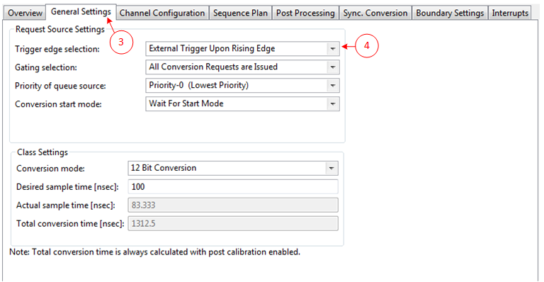
- Goto General Settings Tab.
- Select the Trigger edge as Rising Edge.
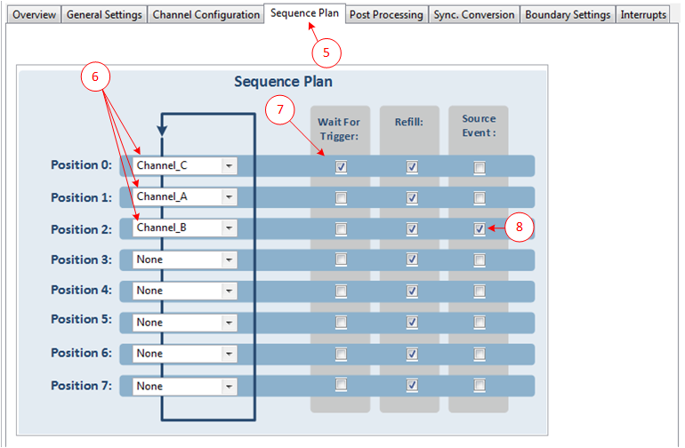
- Goto Sequence Plan Tab.
- Select the Queue Position-0 as Channel-C, Position-1 as Channel-A, Position-2 as Channel_B.
- Select "Wait for Trigger" for Channel-C.
- Select "Source Event" for Channel-B.
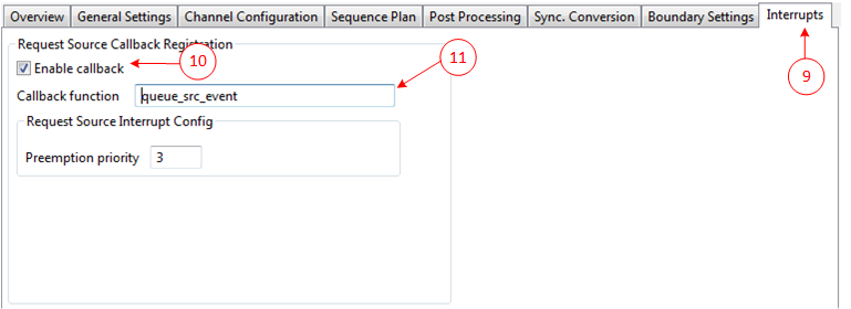
- Goto Interrupts Tab.
- Check the "Enable callback" check box.
- Change the Callback function to queue_src_event.
Manual pin allocation
-
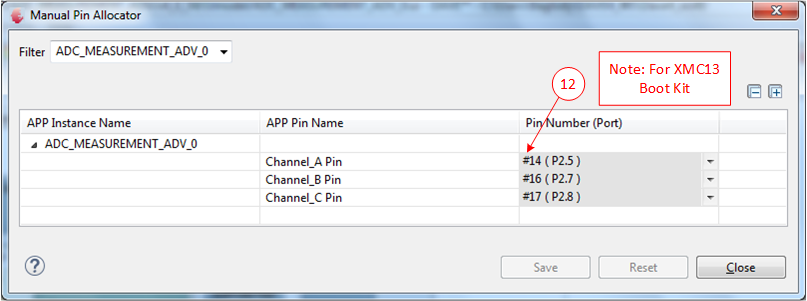
Select the potentiometer Pin present in the boot kit and also the other pins which are available for the select board.
Note:The pin number is specific to the development board chosen to run this example. The pin shown in the image above may not be available on every XMC boot kit. Ensure that a proper pin is selected according to the board.
HW Signal Connections
-
Connect the PWM_0 event_period_match signal to ADC_MEASUREMENT_ADV_0 trigger_input.
Note:Ensure that the period match event in the PWM_0 is enabled.

Generate code
Files are generated here: '<project_name>/Dave/Generated/' ('project_name' is the name chosen by the user during project creation). APP instance definitions and APIs are generated only after code generation.
-
Note: Code must be explicitly generated for every change in the GUI configuration.
Important: Any manual modification to the APP specific generated files will be overwritten by a subsequent code generation operation.
Sample Application (main.c)
 #include <DAVE.h>                 //Declarations from DAVE Code Generation (includes SFR declaration)

 uint16_t resultA,resultB,resultC;

 // Request source event for Channel_B
 void queue_src_event(void)
 {
   // read the results of the conversion
   resultA = ADC_MEASUREMENT_ADV_GetResult(&ADC_MEASUREMENT_ADV_0_Channel_A);
   resultB = ADC_MEASUREMENT_ADV_GetResult(&ADC_MEASUREMENT_ADV_0_Channel_B);
   resultC = ADC_MEASUREMENT_ADV_GetResult(&ADC_MEASUREMENT_ADV_0_Channel_C);
 }

 int main(void)
 {
   DAVE_STATUS_t status;

   status = DAVE_Init();           /* Initialization of DAVE APPs  */


   if(status == DAVE_STATUS_FAILURE)
   {
     /* Placeholder for error handler code. The while loop below can be replaced with an user error handler. */
     XMC_DEBUG("DAVE APPs initialization failed\n");

     while(1U)
     {

     }
   }

   // Start the PWM trigger.
   PWM_Start(&PWM_0);
   while(1U)
   {

   }
 }
Build and Run the Project
Observation
The measurement is started after initialization and waits for a hardware trigger. With a hardware trigger Channel_C, Channel_A and Channel_B are converted in this sequence. The source event for Channel_B is enabled and execute the ISR queue_src_event(void). In this ISR the results of Channel_A, Channel_B and Channel_C are stored in "resultA", "resultB" and "resultC" variables. A new sequence is started with the next hardware trigger
Use case 4:
The use case illustrates synchronous conversions.
The synchronous conversion is used when one or more slaves are busy while the master starts a request. In this case the master group cancel the slave group conversion, wait until all slaves are ready and starts a conversion. This provides an exact synchronous conversion.
In this use case one ADC_MEASUREMENT_ADV APPs are used. The APP is used to configure the master which is controlled by a hardware trigger. The result event of the master is generating an interrupt where both results are read.
The ADC_MEASUREMENT_ADV APP for master is using the "ADC_QUEUE_APP" with a hardware trigger input. A Sync. Conversion with one slave is configured, see following configuration. The ADC_MEASUREMENT_ADV APP for master is triggered by a hardware trigger. See Use Case 3 for configuration.
Instantiate the required APPs
Drag an instance of ADC_MEASUREMENT_ADV APP, one instance of PWM APP and INTERRUPT APP. Update the fields in the GUI of the APP with the following configuration.
Configure the APP:
ADC_MEASUREMENT_ADV_0 APP:
- Set the request source to ADC_QUEUE_APP .
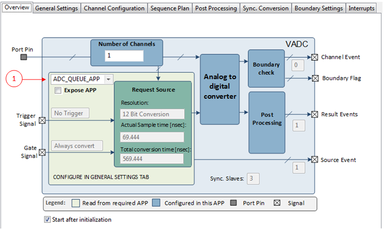
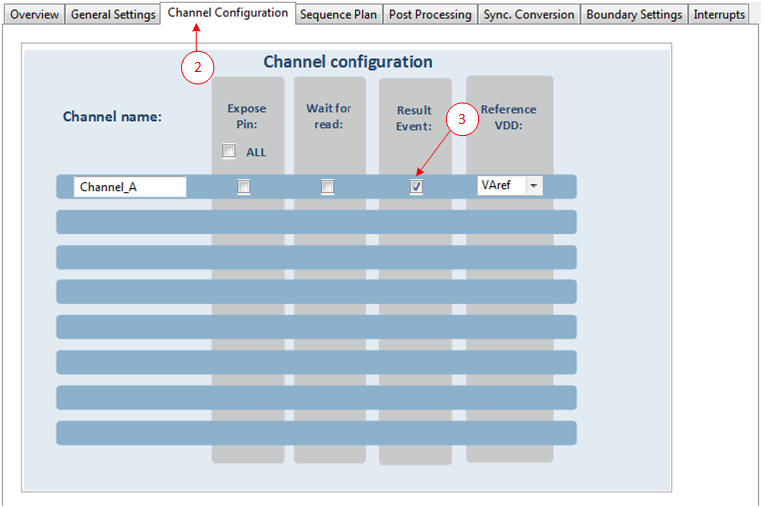
- Goto Channel configuration Tab.
- Enable the result event for the Channel_A.
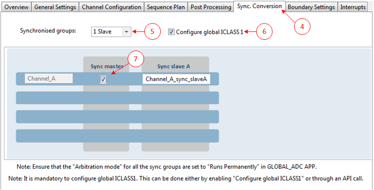
- Goto Sync. conversion Tab.
- Select the synchronized groups to "1 Slaves" .
- Enable the Configure global ICLASS-1.
- Enable the sync master checkbox for Channel_A.
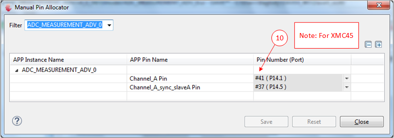
Manual pin allocation
-
Select the potentiometer Pin present in the boot kit and also the other pins which are available for the select board.
Note:The pin number is specific to the development board chosen to run this example. The pin shown in the image above may not be available on every XMC boot kit. Ensure that a proper pin is selected according to the board.
HW Signal Connections
-
Connect the PWM_0 event_period_match signal to ADC_MEASUREMENT_ADV_0 trigger_input.
Note:Ensure that the event_period_match in the PWM_0 is enabled.

- Connect the ADC_MEASUREMENT_ADV_0 event_res_Channel_A signal to INTERRUPT_0 sr_irq.

Generate code
Files are generated here: '<project_name>/Dave/Generated/' ('project_name' is the name chosen by the user during project creation). APP instance definitions and APIs are generated only after code generation.
-
Note: Code must be explicitly generated for every change in the GUI configuration.
Important: Any manual modification to the APP specific generated files will be overwritten by a subsequent code generation operation.
Sample Application (main.c)
 #include <DAVE.h>                 //Declarations from DAVE Code Generation (includes SFR declaration)

 uint16_t resultA,result_slaveA,result_slaveB,result_slaveC;

 // Result event for Channel_A
 void UserIRQHandler(void)
 {
   // read the results of the conversion
   resultA = ADC_MEASUREMENT_ADV_GetResult(&ADC_MEASUREMENT_ADV_0_Channel_A);
   result_slaveA = ADC_MEASUREMENT_ADV_GetResult(&ADC_MEASUREMENT_ADV_0_Channel_A_sync_slaveA);
 }

 int main(void)
 {
   DAVE_STATUS_t status;

   status = DAVE_Init();           /* Initialization of DAVE APPs  */


   if(status == DAVE_STATUS_FAILURE)
   {
     /* Placeholder for error handler code. The while loop below can be replaced with an user error handler. */
     XMC_DEBUG("DAVE APPs initialization failed\n");

     while(1U)
     {

     }
   }

   // start the trigger signal for the ADC_MEASUREMENT_ADV_0
   PWM_Start(&PWM_0);

   while(1U)
   {

   }
 }
Build and Run the Project
Observation
The voltage at sync pins are converted for each rising edge of the PWM signal. The conversion results are stored in "resultA" and "result_slaveA"variables.