|
ADC_MEASUREMENT_ADV
|
Overview
Scope:
This APP measures multiple analog signals using the Versatile Analog to Digital Converter (VADC) peripheral. It provides advanced features such as sequencing, post processing, synchronized measurements and hardware boundary check
Some configurations are set in a required APP (ADC_SCAN or ADC_QUEUE). These configurations are read only in this APP
The features in detailed are:
- Up to 8 analog channels (more with sync. conversion)
- Measures a linear sequence of analog inputs (Scan request source).
- Measures a flexible sequence of analog inputs (Queue request source).
- Supports internal and external consumption of the request sources.
- Software and hardware controlled start of measurements.
- Results post processing with FIFO and Filter.
- Synchronously channels measurement.
- Boundary configurations for channels
- Supports events (Request source event, Result event, Channel event, boundary flag).
Scope delimitation:
To avoid cross configuration, the background request source is not in the scope of this APP. This feature can be added without cross configuration by adding the ADC_MEASUREMENT APP to the project.
Details of provided functionalities:
-
Number of channels and conversion details:
The number of channels can be configured in the APP GUI "Overview". Also the type of conversion can be selected. The conversion details (Timing, Resolution...) are read from required APP.
-
Conversion sequence:
The channel names configured in the APP GUI "Channel Configuration". Also for each channel the "Wait for read" can be enabled.
-
Scan sequence:
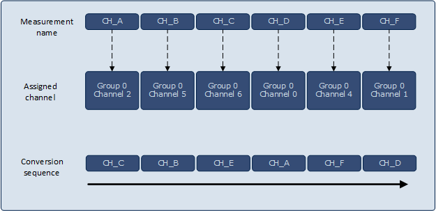
The scan sequence is a linear sequence starting with the highest enabled channel (CH7 to CH0). The assignment of the "Channel name" to the physical channel CHx is done by assigning the channel resource or by assigning the input pin. This is explained with an example as follows:
If 6 measurements are configured in the GUI named as CH_A, CH_B, CH_C, CH_D, CH_E, CH_F. The channels assigned to the measurements is as follows
CH_A = CHANNEL-2
CH_B = CHANNEL-5
CH_C = CHANNEL-6
CH_D = CHANNEL-0
CH_E = CHANNEL-4
CH_F = CHANNEL-1
The order of conversion sequence for these measurements is as shown in the following figure
Figure 1 : Scan Conversion Sequence -
Queue sequence:
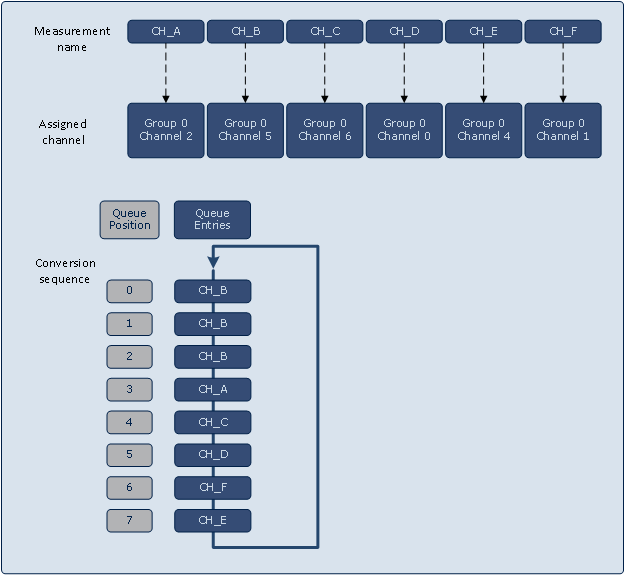
The queue sequence is a flexible 8 stages sequence. Each channel can be placed in any position and also multiple entries of one channel are possible. The TAB "Sequence Plan" in the APP GUI allows configuring the sequence. The assignment of the "Channel name" to the physical channel CHx is done by assigning the channel resource or by assigning the input pin. This is explained with an example as follows:
If 6 measurements are configured in the GUI named as CH_A, CH_B, CH_C, CH_D, CH_E, CH_F. The channels assigned to the measurements is as follows:
CH_A = CHANNEL-2
CH_B = CHANNEL-5
CH_C = CHANNEL-6
CH_D = CHANNEL-0
CH_E = CHANNEL-4
CH_F = CHANNEL-1
And the Queue sequence is selected as follows:
CH_B = CHANNEL-5
CH_B = CHANNEL-5
CH_B = CHANNEL-5
CH_A = CHANNEL-2
CH_C = CHANNEL-6
CH_D = CHANNEL-0
CH_F = CHANNEL-1
CH_E = CHANNEL-4
The order of conversion sequence for these measurements is as shown in the following figure

Figure 2 : Queue Conversion Sequence
-
-
Expose APP:
The APP supports the consumption of the request source inside or outside the APP. This feature shall by selecting the "Expose APP" option in the overview TAB of the APP GUI. If Expose APP is enabled, the APP consumes the required request source APP either ADC_SCAN or ADC_QUEUE depending on the selection being made. If the expose APP option is disabled then the request source will be consumed inside the APP. Use the "Expose APP" option when multiple use case APPs like ADC_MEASUREMENT_ADV and BUCK need to share the request source.
-
Synchronous conversion:
Two or more measurements can be requested at the same time when they share the same trigger. If one of the ADC groups is already converting at this moment this measurement will be delayed compared to the other measurements. In some applications the measurement has to be done completely synchronous. For this case the APP supports the synchronous conversion mode. The synchronous conversion is implemented as master/ slave approach. If one group is a master the following group(s) can be slaves.
To configure a group as sync master the number of slaves need to be selected in the TAB "Sync. Conversion". After this configuration each channel can be configured as master channel. A master channel will allocate the selected amount of slave channels. The master and slave group is different but the channel number is the same. Every time the master channel starts a conversion, the slave channels also start a conversion.
For example G0 is a master group with 1 slave. This makes G1 to a slave group. As soon as "Channel_A" (from G0) is configured as Sync Master and assigned to CH3, G1 CH3 becomes a slave channel. When the master G0 CH3 is requested to convert also the slave G1 CH3 will be converted.
Sync slave channels are named with the <master channel>_slave_<slave token>. Slave channels are exclusive consumed by the APP. The class selection, post processing and boundary configurations are copied from the master to all slaves.
If required, the class configuration can copied via APP API. This API can overwrite a class configuration if it is configured by another APP.
Note: Ensure that the "Arbitration mode" for all the sync groups is set to "Run Permanently" in GLOBAL_ADC APP.
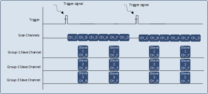
If 6 measurements are configured in the GUI named as CH_A, CH_B, CH_C, CH_D, CH_E, CH_F slaves groups needed as 3(Group-0 is the master). CH_F(from Group-0) and CH_B(from Group-0) are configured as sync master channels. The channels in the master are using scan request source for conversion and the order of conversion is as show in the Figure 1. The sync conversion with scan request source is as shown in the following figure.

Figure 3 : Sync conversion with scan request source -
Result processing:
The APP supports result post processing in the hardware. The post processing options can be selected from the APP GUI tab "Post Processing". The options for post processing include the following options:
-
FIFO buffer
This allows up to 16 stage FIFO buffer for the selected channel. -
Result filtering
Allows either FIR filter or IIR filter for filtering of conversion results. -
Result accumulation
Allows up to 4 accumulations of conversion results. -
Result subtraction
Subtracts the conversion result by the value stored in the GxRES0 register. The result register is not allocated when this mode is selection.
-
FIFO buffer
-
Limit Checking (Boundary):
The APP supports result monitoring with limit checking.
In normal mode the converted value is automatically checked with two boundary values. If required, a channel event is generated on every result or if the result is inside or outside the boundary.
In fast compare mode the result is checked with a compare value. In this mode a channel event can be generated if the result is lower or higher the compare value or if the value is crossing the compare value.
The fast compare mode can be selected in the required APP ADC_SCAN or ADC_QUEUE. Additional for both modes and up to 4 channels a boundary flag is available.
-
Interrupt Notifications:
-
Result event:
A notification or an event is generated when a new valid result is present in the result register -
Channel event:
A notification or an event is generated when either a channel has finished its conversion or the channel's converted result is inside/outside the boundary values. -
Request source interrupt:
A interrupt is generated when all the channels are converted once. For a scan request source the interrupt is generated after the least channel number gets converted. For a queue request source the interrupt is generated after a specific entry finishes its conversion.
-
Result event:
APP Structure
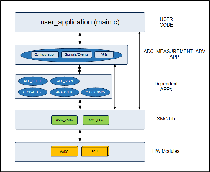
Figure 4 , shows how the APP is structured in DAVE. XMC controllers provides the VADC module for analog to digital conversion. The XMC Lib layer provides abstraction for these hardware modules. The ADC_MEASUREMENT_ADV APP uses VADC and SCU LLDs and other dependent APPS such as ADC_QUEUE, ADC_SCAN, GLOBAL_ADC ,ANALOG_IO and CLOCK_XMCx for the functional execution.

Limitations:
- Channel events are only supported for boundary channels, hence is limited to maximum 4.
- The sync. slave channel events are not available for signal connection.
- For XMC1x devices when alias feature is used, it causes the gain value to be configured for the source channel and not for the alias channel.
Supported Devices
The APP supports below devices:
- XMC4800 / XMC4700 Series
- XMC4500 Series
- XMC4400 Series
- XMC4300 Series
- XMC4200 / XMC4100 Series
- XMC1400 Series
- XMC1300 Series
- XMC1200 Series
Reference
- XMC4800 / XMC4700 Reference Manual
- XMC4500 Reference Manual
- XMC4400 Reference Manual
- XMC4300 Reference Manual
- XMC4200 / XMC4100 Reference Manual
- XMC1400 Reference Manual
- XMC1300 Reference Manual
- XMC1200 Reference Manual