|
ADC_MEASUREMENT_ADV
|
Architecture Description
The following diagrams represents the internal software architecture of the ADC_MEASUREMENT_ADV APP. The figure shows the consumed hardware resources, dependent APPs and various signals which are exported.
- Figure 1 represents the architecture of the ADC_MEASUREMENT_ADV APP with expose APP option enabled in the GUI.
- Figure 2 represents the architecture of the ADC_MEASUREMENT_ADV APP with expose APP option disabled in the GUI. This configuration consumes the request source inside ADC_MEASUREMENT_ADV itself.
A ADC_MEASUREMENT_ADV APP instance exists in a DAVE™ project with fixed attributes as shown and uses the VADC peripheral's scan or queue request source for converting a channel. This in addition requires the consumption of the GLOBAL_ADC and CLOCK APPS for functional configurations. The ADC_MEASUREMENT_ADV APP also provides output signals, these are described in Table-1.

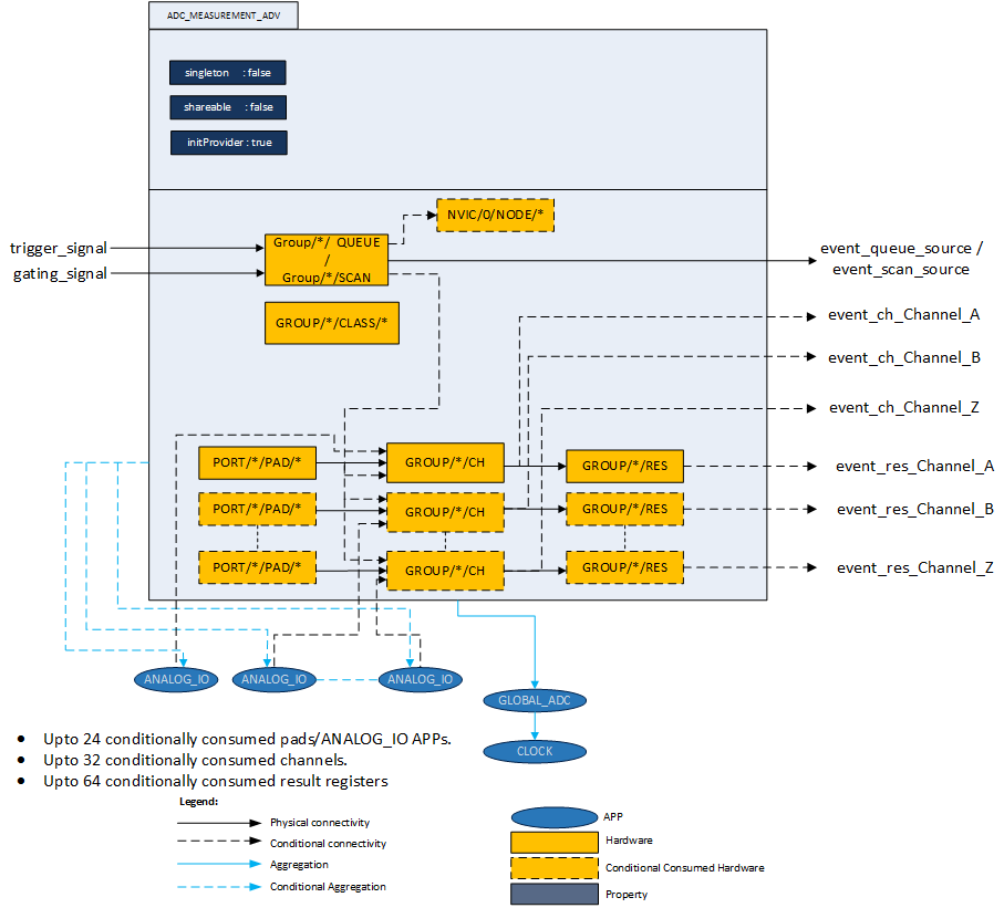
Following are the features of the ADC_MEASUREMENT_ADV APP.
- Pin Sharing
- Result Registers
- Interrupt/Event Generation
- Queue Sequencer
- Insert channels
- Sample and Hold Gain Configuration
- Limit checking(Boundary configuration)
Detailed descriptions are as follows.
-
ANALOG_IO APP is conditionally used by ADC_MEASUREMENT_ADV APP when an "Expose pin"" is selected in the UI. This is applicable for all the channels. By using the ANALOG_IO, the ADC_MEASUREMENT_ADV can share the pin with other APPs such as DAC, ACMP_CONFIG etc.
It is possible to connect the same ANALOG_IO APP to multiple channels. This involves the use of the ALIAS feature of the ADC channels. In this the same pin gets converted by multiple channels from the same group.
For example: Two instances of the ADC_MEASUREMENT_ADV are present in the project. In ADC_MEASUREMENT_ADV_0, 3 channels are used from group-0 and in ADC_MEASUREMENT_ADV_1 another 3 channels are used from Group-1. The example is taken with reference to XMC4500. The pins and channels distribution are shown in the following figure.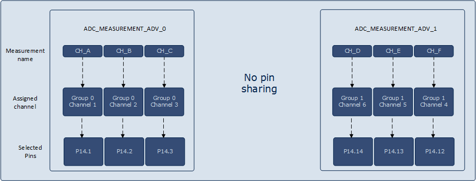
Figure 3 : Pins and channel consumption without ANALOG_IO The alias feature of the VADC allows the Channels 0 and 1 to convert any pin available in the same group. In XMC4500 the pin P14.7 is only connected to Channel-7 of Group-0. With the alias feature we can use the Group-0 Channel-0 to convert P14.7.
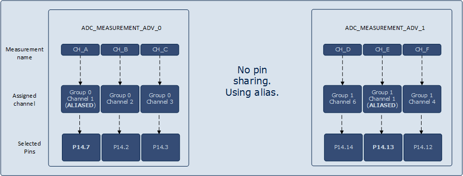
Figure 4 : Pins and channel consumption with alias The alias feature of the VADC allows the conversion of any given pin of the group by the alias channels Channel-0 or Channel-1. This means that the Channel-0 and Channel-1 can convert not only the pins assigned to it but also the other pins available for the entire group. This feature can be used to convert a pin multiple times. In order to do this a pin must get shared with the other channels as well. This is only possible through the consumption of the ANALOG_IO APP. The following figure depicts how the channel numbers get changed when the same pin is being shared between channels.
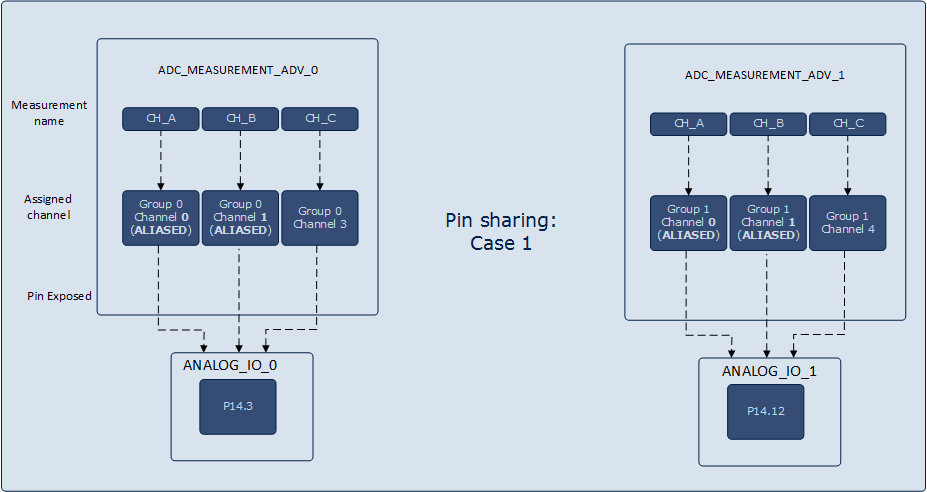
Figure 5 : Pins and channel consumption with ANALOG_IO with a group In different groups of the VADC the channels can have the same pin number. For example in XMC4500 P14.3 is shared between Group-0 Channel-3 and Group-1 Channel-3. Thus two instances of the ADC_MEASUREMENT_ADV APP can convert the same pin. The following figure shows that it is possible to connect the Group-1 Channel-3 to the ANALOG_IO that is consuming P14.3. With the alias feature in the Group-1 is also possible to convert that pin using Group-1 Channel-0 and Group-1 Channel-1.
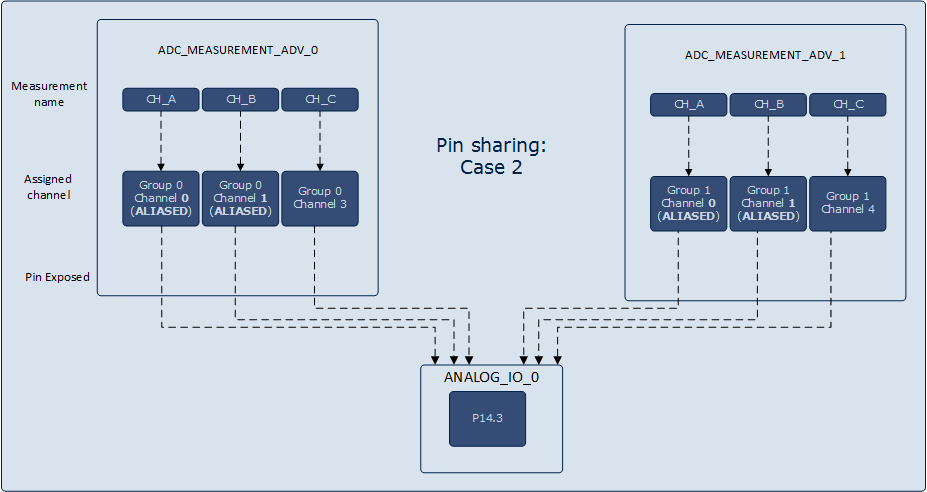
Figure 6 : Pins and channel consumption with ANALOG_IO shared between groups -
Each channel is mapped to one result register(excluding FIFO related configuration). There are 3 different categories of result registers based on different functions it provides.
- result_adv: Provide boundary flag outputs.
- result_filter: Provide filtered output.
- result: Provide accumulation(1x, 2x, 3x, 4x)/subtraction mode.
In ADC_MEASUREMENT_ADV APP the result_adv is used when Boundary is used for Normal Comparison Mode. The result_filter is used when result post processing requires Result Filtering Mode .This is either FIR (Finite Impulse Response) or the IIR(Infinite Impulse Response) filters. The result is used when ever whenever Standard Data Reduction Mode or Subtraction Mode is selected.
-
-
Request source interrupt:
In the Interrupts TAB the ADC_MEASUREMENT_ADV doesn't consume a NVIC node for interrupt. But it uses a callback registration mechanism that is called whenever the request source interrupt is raised. This callback is registered with the request source APP, ADC_QUEUE/ADC_SCAN. The callback is registered in the queue/scan entry by considering the following rules.
- For queue request source the callback would be registered to the entry that has the "Source event" enabled in the Sequence Plan TAB.
- For scan request source the callback is registered with the lowest numbered channel number. Since the lowest channel numbered entry is the last channel to get executed in the scan sequence.
-
Result Event:
Receive an event every time a new result is available in the result register. This event has to be enabled in the "Channel Configuration" TAB. To generate an interrupt from this event, connect the result event signal from the ADC_MEASUREMENT_ADV APP to INTERRUPT APP using the H/W Signal connections. This setup would provide result interrupts for the channels.
-
Channel Event:
This event has to be enabled in the "Boundary Settings" TAB. To enable the channel events, select the channel event combo box for the required channel. To generate an interrupt from this event, connect the result event signal from the ADC_MEASUREMENT_ADV APP to INTERRUPT APP using the H/W Signal connections.
In Normal Conversion Mode it is possible to get a channel event only if the converted value is inside/outside the boundary values or on each new result. The boundary values must be configured using the API ADC_MEASUREMENT_ADV_SetBoundary().
In Fast Compare Mode it is possible to get a channel event only if the measured value is above or below a compare value, or if it crosses the compare value. The compare value is located in the result register and must be configured with the API ADC_MEASUREMENT_ADV_SetFastCompareValue()
-
-
In the Queue sequence it is possible to have a flexible sequence of channels for conversion.
The "Sequence Plan" allows a flexible configuration of the sequence. Each Channel can be placed on any position. Also multiple selections are allowed. Additional for each position the configurations "Wait for Trigger", "Refill" and "Source Event" are available. With the "Wait for Trigger" "configuration" the queue is waiting for a trigger before the selected channel is converted. The "Refill" option allows a one time measurement. This position is not refilled in the queue and will not execute in the next rounds. The "Source Event" configuration will execute a source event when the conversion is finished.
The following examples explain the usage of the "Wait for Trigger" and "Refill" configuration.
In the first example the sequence is starting with CH_C. This channel has the configuration "Wait for Trigger" therefore the sequence is waiting for a Trigger before it starts with the conversion of CH_C. No other channel is configured with "Wait for Trigger" therefore the sequence is immediately continuing with the conversion. When the sequence is reaching the end all channels with "Refill" are refilled and the sequence starts again as new. In this case it is waiting again for a trigger.
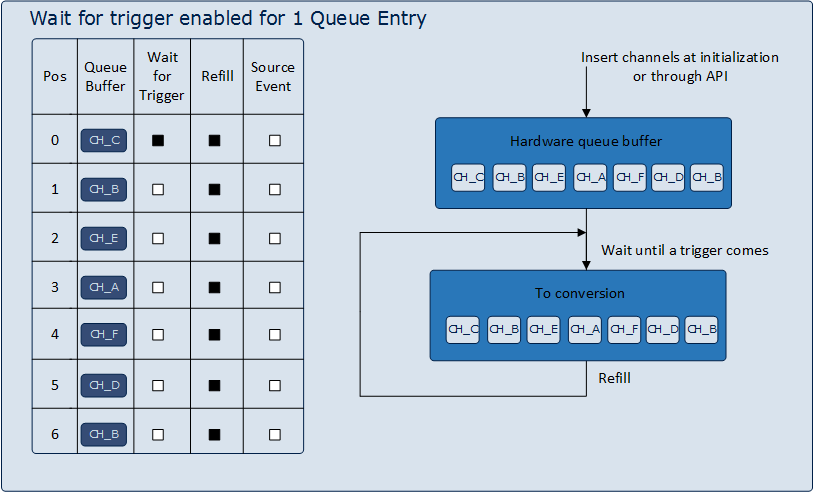
Figure 7 : Queue sequence: Wait for trigger enabled for 1 Queue Entry In the second example additional CH_A is configured with "Wait for Trigger". This results in a two steps sequence. First the sequence is waiting for a trigger, after this trigger CH_C, CH_B and CH_E are converted. Now the sequence is again waiting for a trigger to continue with CH_A. After a trigger CH_A, CH_F, CH_D and CH_B are converted. Hence all channels provide the configuration "Refill" the sequence is repeated.
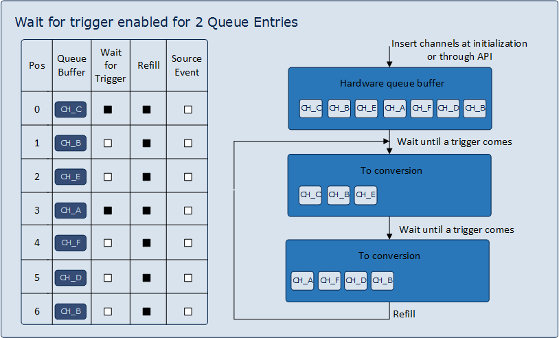
Figure 8 : Queue sequence: Wait for trigger enabled for 2 Queue Entries In the third example again only CH_C provides a "Wait for Trigger" configuration but know don't has a "Refill" configuration. This means the sequence is waiting for a trigger. After the trigger it start with the conversion of CH_C and continuous with all other channels. At the end of the sequence all channels with "Refill" configuration are refilled. Hence CH_C don't has a "Refill" it will not copied in the sequence. This means after the second round there is no entry with "Wait for Read" and the sequence repeat endless.
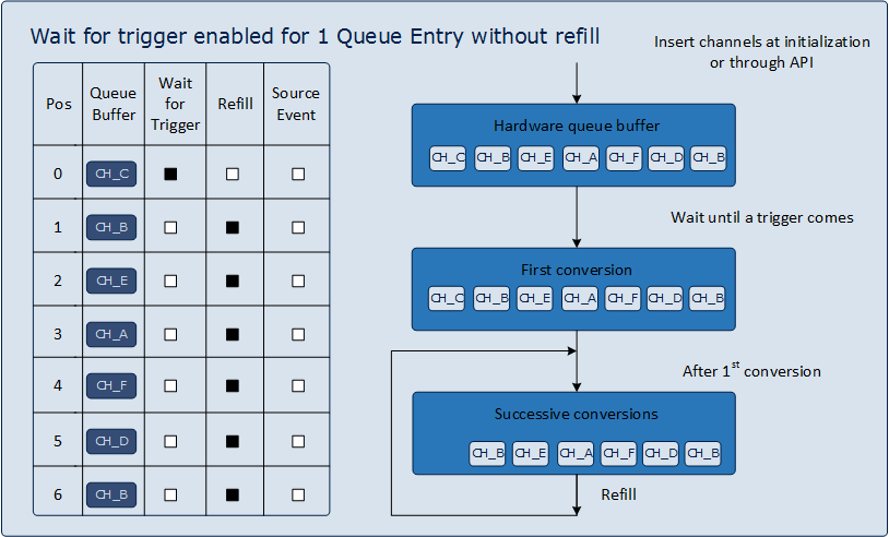
Figure 9 : Queue sequence: Wait for trigger enabled for 1 Queue Entry without refill -
The insert operation in ADC_MEASUREMENT_ADV binds the channels to the selected request source in the hardware.
Since the ADC_QUEUE is shared it is possible to assign the same queue position from other instances of ADC_MEASUREMENT_ADV (or from other APPs). In order to prevent such operations, a MACRO is constructed with the following format.
VADC_QUEUE_GROUP_<group_number>_POSITION_<position_number> .
This would prevent the APPs that are sharing the ADC_QUEUE APP from trying to push a queue entry into the same location. If the same position is used a error message is displayed. If such a error message is received then the queue sequence needs to be modified appropriately in the GUI.
-
ADC_QUEUE
When a ADC_MEASUREMENT_ADV_InsertChannels() API is invoked or the GUI check box "Insert channels at initialization" is enabled with the "Wait for Trigger", the channels will wait until a trigger event occurs. A trigger event can be either a ADC_MEASUREMENT_ADV_StartConversion() or an external trigger edge. When a trigger event occurs the particular channel will go for conversion.
When a ADC_MEASUREMENT_ADV_InsertChannels() API is invoked or the GUI check box "Insert channels at initialization" is enabled without the "Wait for Trigger", The channel being inserted will get converted immediately. And if the refill is enabled for the channel then it will continuously keep converting. -
ADC_SCAN
When a ADC_MEASUREMENT_ADV_InsertChannels() API is invoked or the GUI check box "Insert channels at initialization" is enabled, the channels will be inserted into the hardware. There these channels will continue to wait until a trigger event occurs. A trigger event can be either a ADC_MEASUREMENT_ADV_StartConversion() or an external trigger edge. The trigger event will make all the channels to go for conversion. When all the channels are converted it will go back to wait state when "continuous conversion" is disabled. If "Continuous conversion" is enabled the last channel to get converted will trigger all the channels to get converted again.
-
-
Sample and Hold Gain Configuration:
The gain related configuration is applicable for only the XMC1x series. This feature allows the input signal to be amplified by the required factor. The gain values can be selected in the GUI for the required channel or by invoking the API ADC_MEASUREMENT_ADV_SetChannelGain(). The following example explains how the gain is configured when alias feature is used. The following figure explains the gain configuration by taking 3 channels as an example. The configuration is as follows, CH_A is Group-0 Channel-3, CH_B and CH_C are the alias channels which consume group-0 channel-0 and group-0 channel-1. CH_A and CH_B need gain of 1:1 and CH_C needs 1:3 as the gain ratio. The source channel in this case is Group-0 Channel-3 and the source pin is P14.3 and the other 2 are aliased to this channel. When alias feature is used and gain configuration is needed for the alias channel it is necessary to configure the gain of the source channel rather than the gain of the alias channel. In this example in-order to configure the gain for the CH_C it is necessary to configure the gain in the source channel i.e. group-0 channel-3. Due to such a configuration of the SHS the CH_A and CH_B would also convert with a gain factor of 1:3.
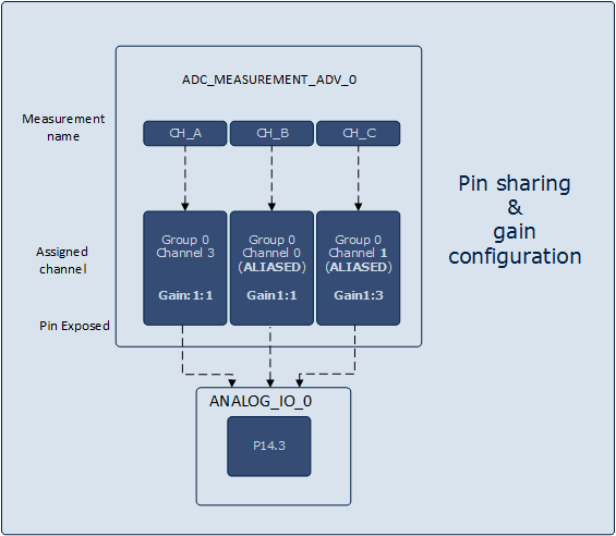
Figure 10 : Sample and Hold gain configuration example with alias enabled -
Limit checking(Boundary configuration):
The Limit checking can automatically compare each conversion to an upper or lower bound values. Accordingly a channel event can be triggered if the result is inside/outside the user-defined band. This limit checking can only be done by specific registers with boundary being configured in GxBOUND or GLOBBOUND. In XMC45 device the limit checking can be done the first 4 channels in each group and in all the other devices the limit checking is done by the first 4 result registers in each group. Hence in the UI the boundary configuration is limited to only 4.
The Boundary values can only be configured by invoking the API ADC_MEASUREMENT_ADV_SetBoundaryUpper() and ADC_MEASUREMENT_ADV_SetBoundaryLower(). These API would configure the respective boundary registers mentioned in the "Boundary Settings" Tab in APP's GUI.
Note: The value to be configured in the boundary registers have to be left aligned compare values. For example, a compare value in 10 bit resolution is 500 in order to configure this in the boundary registers it has to be first left aligned(left alignment is done by left shift operation). After the left shift operation the resulting value is 2000 this value has to be passed as an argument into the ADC_MEASUREMENT_ADV_SetBoundaryUpper() or ADC_MEASUREMENT_ADV_SetBoundaryLower() API.
Signals:
The following table provides all APP signals for connection.
Table 1: APP IO signals
Signal Name Input/Output Availability Description event_res_channel_x
Where channel_x represents the channels that are being used.Output Unconditional Result event for channel_x:
- It can be connected to INTERRUPT APP to generate the interrupt after the result is generated by a particular channel_x.
- The result event is available after the check box in the UI "Result event" for the particular channel is enabled.
- The channel_x can be configured in the "Channel Configuration" Tab of the APP GUI.
event_ch_channel_x
Where channel_x represents the channels that are being used.Output Unconditional Channel event for channel_x:
- It can be connected to INTERRUPT APP.
- The channel event is available after the combo box selection in the UI "Boundary Settings" for the particular channel is enabled.
- The label channel_x can be configured in the "Channel Configuration" Tab of the APP GUI.
bound_fl_channel_x
Where channel_x represents the channels that are being used.Output Conditional Boundary flag output for channel_x:
- It can be connected to other peripherals like CCU / POSIF / ERU etc.
- The boundary flag signal is available only when the combo box selection in the UI "Boundary Settings" for the particular channel is enabled.
- The label channel_x can be configured in the "Channel Configuration" Tab of the APP GUI.
channel_x_input
Where channel_x represents the channels that are being exposed.Input Conditional Input connection from ANALOG_IO APP pin to group channel:
- The pin to channel connection is visible only when "Expose Pin" option is selected for a channel configured under "Channel Configuration TAB".
- The Expose option allows the pin to be shared between peripherals.
- The label channel_x can be configured in the "Channel Configuration" Tab of the APP GUI.
channel_x_slavey_input
Where channel_x represents the slave channels that are being exposed.Input Conditional Input connection from ANALOG_IO APP pin to slave group channel:
- The pin to channel connection is visible only when "Expose Pin" option is selected for a synchronous channel configured under "Channel Configuration TAB".
- The Expose option allows the pin to be shared between peripherals.
- The label channel_x can be configured in the "Channel Configuration" Tab of the APP GUI.
channel_x_sel
Where channel_x represents the channels that are being used.Input Unconditional Input connection from request source APP (ADC_SCAN / ADC_QUEUE) to channel:
- It selects a particular group channel and establishes a connection from group request source to the selected channel.
- The label channel_x can be configured in the "Channel Configuration" Tab of the APP GUI.
Timing Calculations:
ADC_MEASUREMENT_ADV APP uses the following equations to calculate the sample time and Total conversion time.
Refer the reference manual for the detailed information.
-
Total Conversion time: XMC4000 devices
Note: PC value is configured as 2 i.e with post calibration always enabled.
If post calibration is disabled ( in GLOBAL_ADC APP), the total conversion time will be reduced by 2/fADC (GLOBAL_ADC APP).-
Sample Time:
Actual Sample Time = (2 + STC) * tADCI
where,
STC   : Sample time control (Value - 0 to 256)
fADCI : Analog clock frequency
tADCI = 1/fADCI
-
Standard Conversion Mode:
Total Conversion time =  (2 + STC + N + DM + PC) * tADCI + 2 * tADC
Where,
N       = 8, 10, 12 for n bit resolution.
tADC    = ADC module clock = system clock
tADCI   = Analog clock
STC     = Sample time control (Value - 0 to 256)
DM      = The selected duration of the MSB conversion (DM = 0 or 1)
PC      = The post-calibration time PC, if selected (PC = 2, otherwise 0)
-
Fast Compare Mode:
Total Conversion time = (2 + STC + 2) * tADCI + 2 * tADC
Where,
tADC    = ADC module clock = system clock
tADCI   = Analog clock
STC     = Sample time control (Value - 0 to 256)
-
Sample Time:
-
Total Conversion time: XMC1000 devices
- "Total conversion time" for XMC1400/XMC1300/XMC1200 devices are calculated with post calibration.
-
Sample Time:
Minimum sample time is calculated to in accordance with Errata ADC_AI.H007. To ensure proper operation of the internal control logic, tS must be at least four cycles of the prescaled converter clock fSH, i.e. tS >= 4 tCONV x (DIVS+1).Actual Sample Time(tS) = (2 + STC) * tADCI where, STC : Sample time control (Value - 0 to 256) fADCI : Analog clock frequency tADCI = 1/fADCI
-
Standard Conversion Mode:
Total Conversion time = ( 2 + STC) * tADCI + (4 * tSH) + ( N + 8) * tSH + (5 * tADC) + (12 * tSH)
Where,
N       = 8, 10, 12 for n bit resolution.
tSH     = Sample and Hold clock (Converter clock time period)
tADC    = ADC module clock = system clock
tADCI   = Analog clock
STC     = Sample time control (Value - 0 to 256)
tSH = tCONV * (DIVS + 1)
Where,
tSH     = Sample and Hold clock (Converter clock time period)
tCONV   = Converter clock time period (SHS Clock).
DIVS   = Divider Factor for the SHS Clock
-
Fast Compare Mode:
Total Conversion time = (FCRT + 1) * 2 * tADCI + ( 2 + STC)*tADCI
Where,
FCRT    = Fast Compare Mode Response Time (Value - 0 to 15)
tSH     = Sample and Hold clock (Converter clock time period)
tADCI    = Analog clock
STC     = Sample time control (Value - 0 to 256)
Note: FCRT value is configured as 0.