|
DIGITAL_IO
|
Usage
The below example demonstrates LED Toggling.
Hardware requirement:
- XMC4000 Application Kit : CPU_45A-V3(CPU Board XMC4500 General Purpose).
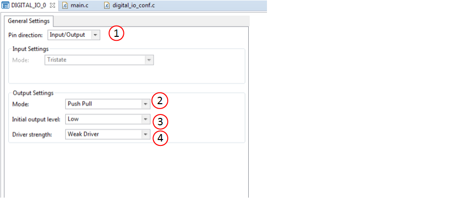
Step 1: Instantiate APP and select Pin direction as Input/Output.
Step 2:Select Mode Push-pull.
Step 3:Select Initial output level to Low.
Step 4:Select Desired Driver strength to Weak Driver.(only available for XMC4X device).
Step 5:Select pin by using Manual Pin Allocator.(Figure shows for XMC4500 device).


Generate code
Files are generated here: `<project_name>/Dave/Generated/' (`project_name' is the name chosen by the user during project creation). APP instance definitions and APIs are generated only after code generation.
Note: Code must be explicitly generated for every change in the GUI configuration.
Important: Any manual modification to APP specific files will be overwritten by a subsequent code generation operation.
Sample Application (main.c)
 #include <DAVE.h>            //Declarations from DAVE Code Generation (includes SFR declaration)
 int main(void)
 {
   DAVE_STATUS_t status;
   uint32_t delay_count;;
   status = DAVE_Init();  //(DAVE_STATUS_t)DIGITAL_IO_Init(&DIGITAL_IO_0) is called within DAVE_Init()
   if(status == DAVE_STATUS_SUCCESS)
   {
    XMC_DEBUG("DAVE Apps initialization success\n");
   }
   else
   {
    XMC_DEBUG(("DAVE Apps initialization failed with status %d\n", status));
    while(1U)
    {
    }
   }
   //Placeholder for user application code. The while loop below can be replaced with user application code.
   while(1U)
   {
    DIGITAL_IO_ToggleOutput(&DIGITAL_IO_0); //toggles level at pin
    for(delay_count = 0;delay_count<0xfffff;delay_count++);
   }
   return 1U;
 }
Build and Run the Project
Observation :
Observe LED1(P3.9) is blinking.