4. Building and RunningTinyCLR
From TinyCLR
4. Building and Running TinyCLR
In this section, we shall describe the way to build, download and execute SH7216_RSK solution available in the porting kit.
4.1 How to Build
1) Using Command-line prompt, change the directory to “Solutions\SH7216_RSK”
C:\MicroFrameworkPK_v4_1>cd solutions\SH7216_RSK
2) Run
Msbuild dotnetmf.proj /t:build /p:flavor=debug
Flavor: <debug|release|rtm>
If you want to debug your program using E10A-USB Emulator, please specify “debug” for “flavor” option.
4.2 Board switch settings
There are three DIP switches located on the CPU board. The function of each switch and its connection are shown below:
Table 4.1 Switch settings
|
SW-5 |
Default Setting |
Function |
|
|
1 |
ON |
OFF |
Changes the operating mode of the MCU (U1, Pin-134) |
|
2 |
ON |
OFF |
Changes the operating mode of the MCU (U1, Pin-153) |
|
3 |
ON |
OFF |
Changes the operating mode of the MCU (U1, Pin-152) |
|
4 |
ON |
OFF |
Changes the operating mode of the MCU |
|
SW-6 |
Default Setting |
Function |
|
|
1 |
ON |
OFF |
Connected to analog input AN4 via “R156”*. |
|
2 |
ON |
OFF |
Connected to analog input AN5 via “R155”*. |
|
3 |
ON |
OFF |
Connected to analog input AN6 via “R154”*. |
|
4 |
ON |
OFF |
Connected to analog input AN7 via “R158”*. |
|
SW-7 |
Default Setting |
Function |
|
|
1 |
ON |
OFF |
Sets up the Ethernet Phy (U5) in isolate Mode*. |
|
2 |
ON |
OFF |
Sets up the Ethernet Phy (U5) in repeater Mode*. |
|
3 |
ON |
OFF |
Sets up the speed of the Ethernet Phy (U5) to 100Mbps*. |
|
4 |
ON |
OFF |
Sets up the Ethernet Phy (U5) in full duplex Mode*. |
|
5 |
ON |
OFF |
Sets up the Ethernet Phy (U5) in Auto-negotiation Mode*. |
|
6 |
ON |
OFF |
Sets up the Ethernet Phy (U5) in LDPS (Link down Power saving) Mode*. |
*Refer to schematic for detailed connectivity information.
4.3 Download using E10A-USB
1) Setup the E10A-USB Emulator
Install the E10A-USB Emulator software into your PC.
During install, you should select the device group for E10A-USB then specify “Super H RISC engine family SH-2A device group”
2) How to start downloading using E10A-USB
Extract the HEW workspace for SH7216 from file SH7216_RSKworkspace.zip at any place in your PC Or create a new workspace for SH7216 using HEW.
In the following instructions, we will assume it is installed in “c:\workspace”
Start the Hew with choosing below menu
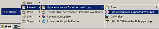
Figure 4.1 Hew menu
Then Hew will be show up and you can see below dialog box.
Specify the workspace as below, and press OK button.
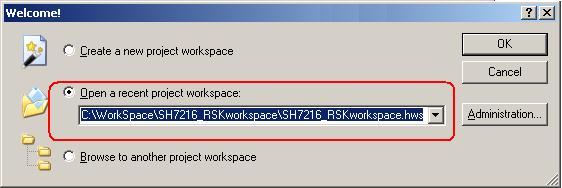
Figure 4.2 Welcome dialog box
In below dialog box, set options like below.
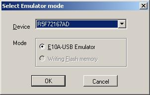
Figure 4.3 Select Emulator mode dialog box
When below message shows up, reset the target board by pressing the reset button on the board and then press OK button.
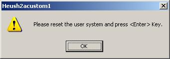
Figure 4.4 Heush2acustom1 dialog box
When below message shows up, enter clock 12.50 MHz as shown below and then press OK button.
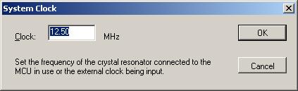
Figure 4.5 System clock dialog box
When below message shows up, enter E10A as shown below and then press OK button.
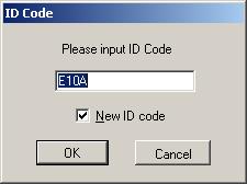
Figure 4.6 System clock dialog box
Then Hew/E10A-USB will finish connection with SH7216.
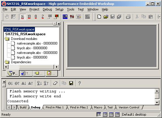
Figure 4.7 Hew window
3) How to download the program to the flash memory
i) Prepare the download module.
Select the [Debug] -> [Debug Settings…] from the menu bar of Hew then below dialog box will show up.

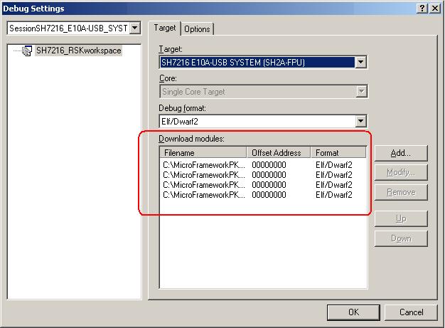
Figure 4.8 Debug Settings dialog box
Here is the definition of download modules. Please change the Path setting for each download module by clicking “Modify” button.
In the option tab, please select option
“Reset CPU after download module”.
ii) Download module to Flash
In order to download, double click on the name of the download module which you want to download to flash.
![]()
Figure 4.9 Hew window
Below message should display during download.
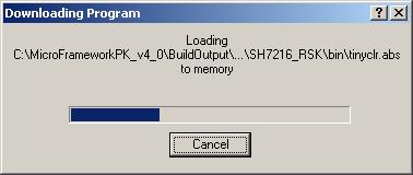
Figure 4.10 Downloading Program dialog box
In the case of downloading NativeSample, please select nativesample.abs instead of tinyclr.abs.
When the download is finished, HEW shall reset the CPU and program counter shall point to address “0x00000800” as shown below.
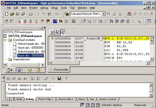
Figure 4.11 Hew window
To actually write into the internal flash execute the program by pressing “F5” key or Select the [Debug] -> [Go] from the menu bar as shown below

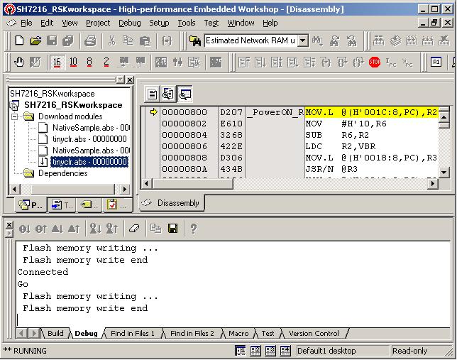
Figure 4.12 Hew window
Here it shows the flash memory write end.
4.4 Running TinyCLR
Hit “Stop” button in the toolbar or Select “Halt Program” option from Debug menu. Disconnect E10A-USB from HEW, power OFF the board and disconnect E10A connection from board.
To verify that TinyCLR is up and running connect the serial port of the target with PC and start the terminal program Tera Term Pro with following settings:
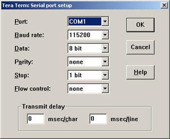
Figure 4.13 Serial port setup
|
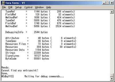
Figure 4.14 Serial terminal
If you can see above messages, congratulations! Your TinyCLR is up and running. This example is the case of using TinyCLR.abs by debug build.
Please note that don’t forget to close Tera Term Pro before proceeding forward.