10. Wiring arrangement
From SH7619 EVB NETMF
10. Wiring arrangement
In this section, the wiring arrangement for hardware for existing LCD driver and Keypad driver is described.
1) Wiring arrangement for LDC panel
The 132 x 176 TFT LCD Display (HD66773R) is interfaced to area CS6B of the SH7619 Bus State Controller (BSC). 3.3V power is provided by the SH7619 board, while 5V power is provided by separate DC power supply connected to the LCD Expansion board. A 40-pin header connector is used for the LCD module interface; the pin assignment for the 40-pin header is shown below.
Figure 10.1 LCD header pin assignment
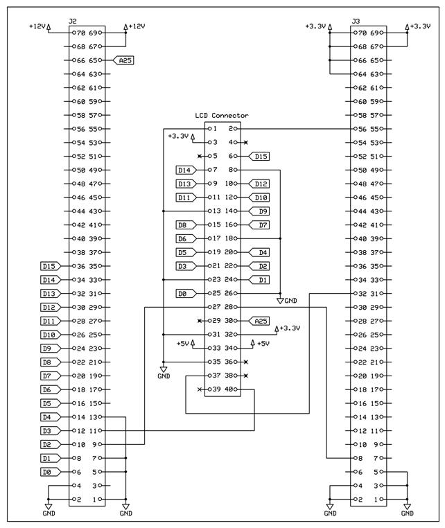
Figure 10.2 Schematic of LCD interface
2) Wiring arrangement for GPIO for Button Keypad
In this Porting Kit, it is assumed that a 25-button keypad matrix is connected to ten GPIOs of the SH7619. Five GPIOs (PC08, PC10, PC09, PC11, and PC13) should be configured for output. The other five GPIOs (PC00, PC01, PC02, PC03, and PC17) should be configured for input and they have pull-up resistors meaning the buttons are active low.
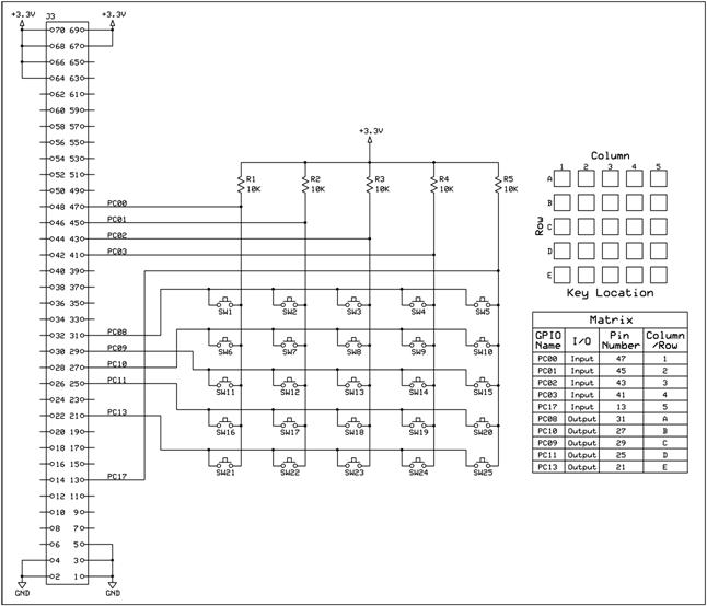
Figure 10.3 GPIO button configuration and perspective orientation
3) Wiring arrangement for secondary Serial Interface
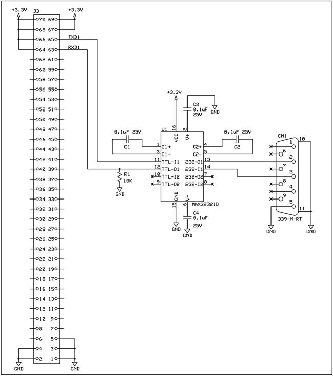
Figure 10.4 Schematic of Secondary Serial Interface