|
RTC
|
Architecture Description

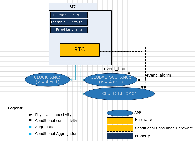
This is the software architecture representation of the RTC APP. The GLOBAL_SCU_XMC, CPU_CTRL_XMC4 and CLOCK_XMC APPs are aggregated. GLOBAL_SCU APP will get consumed whenever event trigger is SCU Interrupt and any periodic event / alarm interrupt is enabled in RTC APP. CPU_CTRL_XMC4 APP will get consumed whenever event trigger is NMI Interrupt and any periodic event / alarm interrupt is enabled in RTC APP. A RTC APP instance exists in a DAVE™ project with fixed attributes and provides output signals for inter-peripheral connections. An instantiated APP (after code generation) generates a specific data structure with the GUI configuration. The name of this data structure can be modified by changing the APP instance label (e.g. changing (default label) RTC_0 to (user defined label) MY_RTC).
Signals:
The following table describes the list of IO signals for RTC APP.
Table 1: APP Input Output signals
| Signal Name | Input/Output | Availability | Description |
| event_timer | Output | Conditional | RTC timer interrupt signal. |
| event_alarm | Output | Conditional | RTC alarm interrupt signal. This signal gets connected to an NVIC node if alarm interrupt is enabled in UI |