Cloth
Introduction
The PhysX clothing feature has been deprecated in PhysX version 3.4.1. The PhysX and APEX clothing features are replaced by the standalone NvCloth library.
Realistic movement of character clothing greatly improves the player experience. The PhysX 3 cloth feature is a complete and high-performance solution to simulate character clothing. It provides local space simulation for high accuracy and stability, new techniques to reduce stretching, collision against a variety of shapes, as well as particle self-collision and inter-collision to avoid the cloth penetrating itself or other cloth instances. The simulation can be offloaded to CUDA capable GPUs for better performance or to run assets at higher resolutions than the CPU is able to handle.
PhysX 3 cloth is a rewrite of the PhysX 2 deformables, tailored towards simulating character cloth. Softbodies, tearing, and two-way interaction have been removed, while behavior and performance for cloth simulation have been improved.
Simulation Algorithm
For one PhysX simulation frame, the cloth solver runs for multiple iterations. The number of iterations is determined by the solver frequency parameter and the simulation frame time. Each iteration integrates particle positions, solves constraints, and performs character and self-collision. Cloth inter-collision is performed once per-frame after all cloth instances in the scene have been stepped forward. Local frame, motion constraints and collision shapes are interpolated per iteration from the per-frame values specified by the user.
Solver Frequency
The size of the iteration time step is inversely proportional to the number of solver iterations:
cloth.setSolverFrequency(240.0f);
The solver frequency is specified as iterations per second. A solver frequency value of 240 corresponds to 4 iterations per frame at 60 frames per second. In general, simulation will become more accurate if higher solver frequency value is used. However, simulation time grows roughly linearly with solver frequency. Typically this value is between 120 and 300.
The number of iterations for each frame is derived using the simulation frequency and the simulation time-step. PhysX tries to handle variable time-steps carefully, by taking variations of the time-step into account during position integration and when applying damping parameters like constraint stiffness. While this reduces the possible jittering artifacts due to varying time step sizes, use of variable time step size is generally not recommended.
Particle Integration
The first step in a cloth iteration predicts the new particle position based on its current position, velocity and external acceleration. While a particle state consists of the current position and the position before the last iteration, the particle velocity in local space can be computed by dividing the position delta by the delta time of the previous iteration.
Local Space Simulation and Inertia Scale
Each PxCloth actor has a transformation that transforms particles from its local space to world space positions. For example:
cloth.setGlobalPose(PxTransform(PxVec3(1.0f, 0.0f, 0.0f));
will change the cloth's world space position to (1,0,0). Now compare that to this function:
cloth.setTargetPose(PxTransform(PxVec3(1.0f, 0.0f, 0.0f));
, which also changes the cloth's position to the same place. So what's different?
PxCloth::setGlobalPose() only moves the cloth, but PxCloth::setTargetPose() also generates acceleration (inertia) due to the position change. The amount by which the local frame acceleration affects the cloth particles can be controlled using an inertia scale, for example to impart half the local frame acceleration to the particles use:
cloth.setInertiaScale(0.5f);
Scaling inertia effects individually per translation and rotation axis is also possible through the family of PxCloth::set*InertiaScale() methods. Limiting the amount that local frame accelerations affect particles can be especially useful for fast moving characters.
Note
Using setGlobalPose() is equivalent to using setTargetPos() when inertia scale is 0. In this case, the cloth does not receive any acceleration due to frame changes.
Constraints
After the particle positions have been integrated, a set of different constraints are solved to simulate stretch, shear and bending forces, as well as to confine the particle movement within a certain region.
Distance Constraints
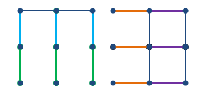
Figure 1. Typical configuration for vertical (left), and horizontal (right) stretching constraints
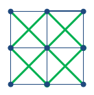
Figure 2. Typical configuration for shearing distance constraints
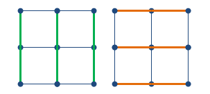
Figure 3. Typical configuration for vertical (left), and horizontal (right) bending constraints, note bending constraints typically span more than one edge in the mesh
One of the most important roles for the cloth solver is to maintain distance between particles so that the cloth does not stretch. This is achieved by applying distance constraints between pairs of particles. The way particles are connected affects how the cloth stretches, compresses, shears, rotates, and bends. PhysX classifies distance constraints into 4 types (see PxClothFabricPhaseType), each of which can be configured with different stiffness parameters.
Below is an example of stiffness settings for each constraint type:
cloth.setStretchConfig(PxClothFabricPhaseType::eVERTICAL, PxClothStretchConfig(1.0f));
cloth.setStretchConfig(PxClothFabricPhaseType::eHORIZONTAL, PxClothStretchConfig(0.9f));
cloth.setStretchConfig(PxClothFabricPhaseType::eSHEARING, PxClothStretchConfig(0.75f));
cloth.setStretchConfig(PxClothFabricPhaseType::eBENDING, PxClothStretchConfig(0.5f));
Sometimes it is desirable that distance constraints are not enforced rigorously. The stiffness parameter allows only correcting a portion of the edge length residual per iteration, for example to reduce the strength of bending constraints. A separate, lower stiffness can be used for edges that are only moderately stretched or compressed. For example, a dress can be made to stretch when the character is taking large steps, but still behave correctly during pirouettes.
The following code sets up the vertical constraints such that when edges are compressed more than 60% or stretched more than 120%, a stiffness of 0.8 will be used. Otherwise a stiffness of 0.4 = 0.8 * 0.5 will be used:
PxClothStretchConfig stretchConfig;
stretchConfig.stiffness = 0.8f;
stretchConfig.stiffnessMultiplier = 0.5f;
stretchConfig.compressionLimit = 0.6f;
stretchConfig.stretchLimit = 1.2f;
cloth.setStretchConfig(PxClothFabricPhaseType::eVERTICAL, stretchConfig);
Note
Stretch settings for horizontal and vertical directions are specified separately. This can be used to handle stretching along the gravity (vertical) direction differently.
Tether Constraints
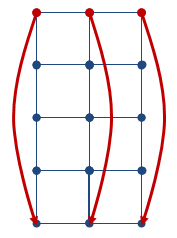
Figure 4. Example tether constraint configuration
The distance constraints are solved only once per iteration without converging completely. The most visible artifact of this approximation is that the cloth becomes stretchy. Increasing solver frequency reduces the stretching, but results in increased simulation time.
PhysX 3.3 introduces tether constraints as a solution to avoid stretchiness under gravity or fast motion. Tether constraints prevent stretching by limiting the distance a particle can move away from their anchor particles. This constraint adds very small amount of computation to the solver, so it is more effective than increasing the number of iterations.
The tether constraints are automatically generated by the cooker when some PxClothMeshDesc::invMasses values are set to zero, telling the cooker that the corresponding particles are non-simulated anchor particles whose positions are provided solely from users. Changing inverse masses after the fabric has been created does not affect which anchor particles are used for the tether constraints.
Motion Constraints
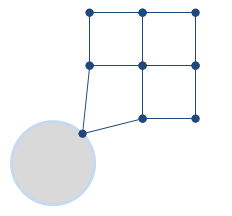
Figure 5. Example motion constraint
One can fully constrain a point to user specified position with zero inverse mass. However, it is sometimes desirable to confine a point within small region around the animated (user specified) position. This allows small details to be generated by simulation, while suppressing any excessive deviation from the desired position.
Motion constraints lock the movement of each particle inside a sphere. For example, an animation system can sketch the overall movement of a cloth while the fine scale details are handled by the cloth simulation.
PxClothParticleMotionConstraint structure holds the position and radius of the sphere for each particle, and motion constraints can be specified as follows:
PxClothParticleMotionConstraints motionConstraints[] = {
    PxClothParticleMotionConstraints(PxVec3(0.0f, 0.0f, 0.0f), 0.0f),
    PxClothParticleMotionConstraints(PxVec3(0.0f, 1.0f, 0.0f), 1.0f),
    PxClothParticleMotionConstraints(PxVec3(1.0f, 0.0f, 0.0f), 1.0f),
    PxClothParticleMotionConstraints(PxVec3(1.0f, 1.0f, 0.0f), FLT_MAX)
};

cloth.setMotionConstraints(motionConstraints);
If the sphere radius becomes zero or negative, the corresponding particle is locked at the sphere center and the inverse particle mass is set to zero for the next iteration. In the above example, the first particle will fully lock to the constraint position, while the second and third particle will remain within the sphere radius. The last particle will not be constrained.
The motion constraint sphere radius can be globally scaled and biased, for example to transition between simulated and animated states. See PxClothMotionConstraintConfig for details.
Separation Constraints
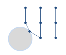
Figure 6. Example separation constraint
Separation constraints work exactly the opposite way to the motion constraints, forcing a particle to stay outside of a sphere. When particle movement is moderately constrained by motion constraints (e.g. sleeves around an arm), separation constraints can be used to represent the character's collision shape more accurately than using capsules alone. For example, separation constraints can be placed slightly inside the character by setting the radius to be the distance from the sphere center to the surface of the character.
See PxClothParticleSeperationConstraint and PxCloth::setSeparationConstraints().
Collision Detection
Each cloth object supports collision with spheres, capsules, planes, convexes (groups of planes) and triangles. By default these shapes are all treated separately from the main PhysX rigid body scene, however collision against other PxScene actors can be enabled using the PxClothFlag::eSCENE_COLLISION flag.
Collision shapes are specified in local coordinates for the next frame before simulating the scene. An independent and complete collision stage is performed as part of each solver iteration, using shape positions interpolated from the values at the beginning and the end of the frame. Sphere and capsule collision supports continuous collision detection and use an acceleration structure to cull far-away particles early in the collision pipeline. Spheres and capsules are therefore the preferred choice to model the character shape, and convexes and triangles should only be used sparingly.
Spheres are defined as center and radius. Note that the radius is specifically allowed to change from frame to frame. The total number of spheres is limited to 32 per cloth.
Capsules are defined by a pair of indices into the spheres array and each sphere may have a different radius thus forming a tapered capsule. Spheres can be shared between multiple capsules, which can be useful for modeling characters (upper and lower leg made up from capsules can share the sphere at the knee). Sharing of spheres also makes the simulation more efficient and robust, so is highly encouraged.
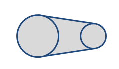
Figure 7. A tapered capsule collision shape formed by two connected spheres
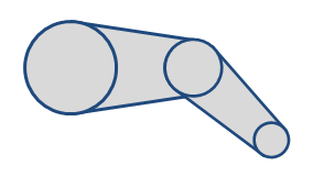
Figure 8. A leg shape formed by using two tapered capsules, each sharing a sphere at the middle
Planes are defined by their normal and distance to origin. They will not be considered for collision unless they are referenced by a convex shape. Convexes reference planes using a mask, where each bit corresponds to an entry in the array of planes. There is a limit of 32 planes per cloth.
Triangle colliders are defined as vertex triplets in counter-clockwise winding order. The triangles should form a closed patch near the cloth for consistent collision handling (each particle collides against its closest triangle expanded to an infinite plane).
The order of planes and triangles should remain unchanged (apart from removing them through the PxCloth::removeCollisionPlane/Triangle() method) as their positions are interpolated between simulation frames.
Continuous Collision Detection
Besides discrete collision which resolves particles inside shapes at the end of each iteration, continuous collision detection is supported and can be enabled by calling:
// Enable continuous collision detection
cloth.setClothFlag(PxClothFlag::eSWEPT_CONTACT, true);
Continuous collision is around 2x more computationally expensive than discrete collision, but it is necessary to detect collision between fast moving objects. Continuous collision analyzes the trajectory of particles and capsules to determine when a contact occurs. After the first time of contact, the particle is moved with the shape until the end of the iteration.
Note
The SIMD collision path handles sets of 4 particles in parallel. It is therefore advantageous to spatially group cloth particles so that they are likely to collide with the same set of shapes.
Virtual Particle Collision
Virtual particles provide a way of improving cloth collision without increasing the cloth resolution. They are called 'virtual' particles because they only exist during the collision processing stage and do not have their position, velocity or mass explicitly stored like regular particles, they can be thought of as providing additional samples on the collision surface.
During collision processing each virtual particle is created from three normal particles using barycentric interpolation. It is then tested for discrete collision like a regular particle and the collision impulse is redistributed back to the original particles using reverse interpolation.
Section Adding Virtual Particles explains the necessary steps to use this feature.
Friction and Mass Scaling
Coulomb friction can be enabled and will be applied for particle and virtual particle collisions by setting a friction coefficient between 0 and 1:
cloth.setFrictionCoefficient(0.5f);
Additionally, there is an option to artificially increase the mass of colliding particles, this temporary increase in mass can help reduce stretching along edges that are being tightly pulled over a collision shape. The effect is determined by the relative normal velocity of the particle and collision shape and a user defined coefficient. A value of 20 is reasonable starting point but users are encouraged to experiment with this value:
cloth.setCollisionMassScale(20.0f);
Self-Collision of a Single Cloth Actor
The particles of a cloth actor can collide among themselves. To enable this self-collision behavior, one should set both self-collision distance and self-collision stiffness to non-zero values:
cloth.setSelfCollisionDistance(0.1f);
cloth.setSelfCollisionStiffness(1.0f);
Self-collision distance defines the diameter of a sphere around each particle, and the solver ensures that these spheres do not overlap during simulations. Self-collision stiffness defines how strong the separating impulse should be.
Self-collision distance should be smaller than the smallest distance between two particles in the rest configuration. If the distance is larger, self-collision may violate some distance constraints and result in jittering.
When such a configuration cannot be avoided (e.g. due to irregular input meshes, etc.), one can assign additional rest positions:
cloth.setRestPositions(restPositions);
Collision between two particles is ignored if their rest-positions are closer than the the collision distance. However, a large collision distance and use of rest positions will significantly degrade performance of self-collision, so should be used sparingly.
Self-collision performance for high-resolution cloth instances can be improved by limiting self-collision to a subset of all particles (see PxCloth::setSelfCollisionIndices()).
Inter-Collision between Multiple Cloth Actors
Different cloth actors can be made to interact with each other when inter-collision is enabled. The parameters for inter-collision are set for all cloth instances of a scene:
scene.setInterCollisionDistance(0.5f);
scene.setInterCollisionStiffness(1.0f);
The definition of distance and stiffness values are the same as self-collision. Cloth instances that specify a particle subset for self-collision use the same subset for inter-collision.
Best Practices / Troubleshooting
Performance Tips
The runtime of the cloth simulation scales approximately linearly with the number of cloth particles and the solver frequency: Simulating a higher resolution mesh with more particles and increasing stretch stiffness and collision handling fidelity with higher solver frequencies increase the time it takes to simulate one frame. Additionally, there is a performance drop somewhere below 3000 particles for the GPU solver as explained in the next section. As a rough guideline, a dozen cloth instances with 2000 particles each and a solver frequency of 300Hz can be simulated in real-time as part of a game.
Convex collision and triangle collision do not use any mid phase acceleration structure, and are therefore slower than sphere and capsule collision.
Self-collision and inter-collision can take a significant amount of the overall simulation time. Consider keeping the collision distance small and using self-collision indices to reduce the number of particles that collide with each other.
Using GPU Cloth
Cloth can be simulated on a CUDA or DirectCompute enabled GPU, by setting one of the corresponding flags:
cloth.setClothFlag(PxClothFlag::eCUDA, true);
cloth.setClothFlag(PxClothFlag::eDIRECT_COMPUTE, true);
The entire cloth solver pipeline is run on the GPU, with the exception of inter-collision. When no supported GPU is available PhysX will issue a warning, and subsequent simulations will be run on CPU.
When the cloth is simulated using CUDA, the GPU simulation results can interop with the graphics API by requesting CUDA device pointers to the particle data:
cloth.lockParticleData(PxDataAccessFlag::eDEVICE);
To take full advantage of the GPU hardware there should be at least as many cloth instances as streaming multiprocessors (SMs). This means it is generally better to simulate clothing as multiple instances (e.g. shirts and skirt) rather than grouped into one instance.
GPU PhysX performance is better when the particle data of a cloth can fit in shared memory. The number of particles that fit into shared memory depends on the number of collision shapes, whether continuous collision or self-collisions are enabled, and also on the GPU version. For GPUs supporting SM 2.0 and above, about 2500-2900 particles fit into shared memory. If particles don't fit into shared memory the cloth solver will automatically stream particles through global memory, which incurs some performance cost.
Furthermore, the limited size of shared memory requires the number of collision triangles to be clamped to 500 when GPU simulation is enabled.
Fast-Moving Characters
Consistent collision handling for fast-moving characters can be difficult. Fast translations and rotations are best handled by tying the cloth local simulation frame to the character transformation. The inertia effects of the local frame transformations can be fine-tuned using the inertia scale settings.
If the cloth tunnels collision shapes during fast character animations, try increasing the solver frequency or enabling swept contacts (see PxClothFlag::eSWEPT_CONTACT).
Avoiding Stretching
Due to the iterative nature of the distance constraint solver, high resolution cloth can stretch undesirably under strong gravity even if the stretch stiffness is set to one. Increasing the solver frequency mitigates the stretching, but tether constraints are usually better suited to eliminate stretching efficiently.
Avoiding Jitter
Under certain configurations, different constraint types can violate each other and over-constrain the particle positions. For example, a motion constraint can move the particle further from the anchor particle than the tether constraint permits, or particles can get pinched between two overlapping collision shapes. Over-constraining particle positions can result in jitter and should be avoided. In some situations jitter can be avoided by increasing the solver frequency or by reducing the corresponding constraint stiffness.
PVD Support
Cloth particle positions, distance constraints, and collision shapes are rendered as points, lines, and wireframes respectively in PVD. The SDK does not have access to the mesh used to create the fabric, and this mesh can't be displayed in PVD either. However, you can display individual sets of distance constraints instead of all at once: set Cloth Phase Mode to Single Phase in the Preferences dialog and use the Cloth Phase slider to pick the phase to display. The Particle Scale slider in the same dialog affects the rendering size of ordinary and virtual cloth particles as well. All properties of a selected cloth object can be viewed in the Inspector panel of PVD.
Snippet Discussion
The following paragraph describes code of the cloth snippet provided with the PhysX SDK.
The cloth constraint connectivity and rest values are stored in a fabric instance (PxClothFabric), separate from the cloth actor (PxCloth). The separation of the constraints from particles allows the same fabric data to be reused for multiple cloth instances, reducing cooking time and storage requirements. PxClothFabricCreate, in the extensions library, creates a fabric from a triangle or quad mesh (see PxClothMeshDesc). The cloth actor itself is created through the physics instance (PxPhysics) and needs to be added to a scene (PxScene) in order to be simulated. Once the cloth actor is created, users can assign simulation settings such as collision data, constraint stiffness, solver frequency and self-collision. The createCloth function in the cloth snippet performs these steps.
The stepPhysics function advances the simulation by one frame. It first updates the cloth local frame, which rotates around the y-axis. The collision shapes are not moving in scene coordinates, but their positions are specified in cloth local coordinates, and therefore need to be updated every frame. The following sections detail some of the available parameters and show how to configure them.
Note
The cloth module has to be registered with PxRegisterCloth on platforms with static linking (non windows) before creating cloth objects. PxCreatePhysics registers all modules by default as opposed to PxCreateBasePhysics.
Filling in PxClothMeshDesc
The first task to create a cloth is to fill in the PxClothMeshDesc structure. The snippet programmatically creates a regular grid of cloth particles connected by a quad mesh. Below is a simpler example on how to create a cloth from a simple mesh consisting of a single quad.
PxClothParticle vertices[] = {
    PxClothParticle(PxVec3(0.0f, 0.0f, 0.0f), 0.0f),
    PxClothParticle(PxVec3(0.0f, 1.0f, 0.0f), 1.0f),
    PxClothParticle(PxVec3(1.0f, 0.0f, 0.0f), 1.0f),
    PxClothParticle(PxVec3(1.0f, 1.0f, 0.0f), 1.0f)
};

PxU32 primitives[] = { 0, 1, 3, 2 };

PxClothMeshDesc meshDesc;
meshDesc.points.data = vertices;
meshDesc.points.count = 4;
meshDesc.points.stride = sizeof(PxClothParticle);

meshDesc.invMasses.data = &vertices->invWeight;
meshDesc.invMasses.count = 4;
meshDesc.invMasses.stride = sizeof(PxClothParticle);

meshDesc.quads.data = primitives;
meshDesc.quads.count = 1;
meshDesc.quads.stride = sizeof(PxU32) * 4;
Each particle is defined by its position in local coordinates and its inverse mass. Setting the inverse mass to zero indicates that the particle is not simulated. Instead, the particle is fixed in local space or kinematically constrained to user specified positions. The inverse mass of simulated particles can normally be set to any fixed positive value.
The PxClothMeshDesc structure allows positions and inverse masses stored in separate arrays or interleaved like in the code above. The mesh can consist of quads or triangles, or both. The cooker prefers quad meshes over triangle meshes when creating constraints and classifying constraint types. The extensions library therefore provides the PxClothMeshQuadifier helper class to extract quads from a triangle mesh.
Creating Fabric
Given the mesh descriptor, a call to PxClothFabricCreate in the extensions library wraps the generation of constraints and the creation of the PxClothFabric structure:
PxClothFabric* fabric = PxClothFabricCreate(physics, meshDesc, PxVec3(0, -1, 0));
The third parameter indicates the direction of gravity, which is used as a hint to determine the direction of 'horizontal' or 'vertical' constraints.
The PxClothFabric class describes internal solver data for a cloth. For example, distance constraints consisting of two particle indices and a rest-length are created by the cooker and stored in the fabric data. Multiple cloth instances of the same mesh can share a single fabric instance.
Creating Cloth
A PxCloth object is created using a fabric instance and the initial particle configuration. Like all actors, the cloth instance is simulated as part of a scene:
PxTransform pose = PxTransform(PxIdentity);
PxCloth* cloth = physics.createCloth(pose, fabric, vertices, PxClothFlags());
scene.addActor(cloth);
The first parameter specifies the initial pose. The second input is the fabric instance created by the cooker. The third input provides initial particle positions and inverse masses. Typically this array is the same as the one referenced by the mesh descriptor used to create the fabric. Note that the rest configuration (such as the rest-length for a distance constraint) is computed from PxClothMeshDesc, so the initial particle positions do not affect rest configuration. The last parameter is a set of flags that allow GPU simulation and continuous collision detection to be enabled. The default is to turn off both options.
Specifying Collision Shapes
The following code illustrates how to add two spheres of different radius and create a tapered capsule between them:
// Two spheres located on the x-axis
PxClothCollisionSphere spheres[2] =
{
    PxClothCollisionSphere( PxVec3(-1.0f, 0.0f, 0.0f), 0.5f  ),
    PxClothCollisionSphere( PxVec3( 1.0f, 0.0f, 0.0f), 0.25f )
};

cloth.setCollisionSpheres(spheres, 2);
cloth.addCollisionCapsule(0, 1);
Planes can be added through PxCloth::addCollisionPlane() method but will not be considered for collision unless they are referenced by a convex shape. For example, the following code shows how to setup a typical upward facing ground plane through the origin:
cloth.addCollisionPlane(PxClothCollisionPlane(PxVec3(0.0f, 1.0f, 0.0f), 0.0f));
cloth.addCollisionConvex(1 << 0); // Convex references the first plane
Planes may be efficiently updated after construction using the PxCloth::setCollisionPlanes() function.
Finally, triangles are added using the PxCloth::setCollisionTriangles() function. For example, the following code adds a tetrahedron made of four triangles:
PxClothCollisionTriangle triangles[4] = {
    PxClothCollisionTriangle(PxVec3(0.0f, 0.0f, 0.0f),
                             PxVec3(1.0f, 0.0f, 0.0f),
                             PxVec3(0.0f, 1.0f, 0.0f)),
    PxClothCollisionTriangle(PxVec3(1.0f, 0.0f, 0.0f),
                             PxVec3(0.0f, 0.0f, 1.0f),
                             PxVec3(0.0f, 1.0f, 0.0f)),
    PxClothCollisionTriangle(PxVec3(0.0f, 0.0f, 1.0f),
                             PxVec3(0.0f, 0.0f, 0.0f),
                             PxVec3(0.0f, 1.0f, 0.0f)),
    PxClothCollisionTriangle(PxVec3(0.0f, 0.0f, 0.0f),
                             PxVec3(0.0f, 0.0f, 1.0f),
                             PxVec3(1.0f, 0.0f, 0.0f)),
};
Note
The snippet adds collision convex and capsule once in the createCloth function, and then updates collision spheres, planes and triangles every frame in the stepPhysics function.
Adding Virtual Particles
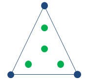
Figure 9. Four virtual particles (green) expressed as the weighted combination of a triangle's particles, virtual particles provide a better sampling of the cloth geometry that improves collision detection.
A virtual particle is defined by 3 particle indices and an index into a weights table, the weights table defines the barycentric coordinates used to create a virtual particle position from a linear combination of the referenced particles. The following is an example weights table that can be used to create a distribution of 4 virtual particles on a triangle:
static PxVec3 weights[] =
{
    PxVec3(1.0f / 3, 1.0f / 3, 1.0f / 3), // center point
    PxVec3(4.0f / 6, 1.0f / 6, 1.0f / 6), // off-center point
};
The code below shows an example of how to set up the virtual particles from a PxClothMeshDesc:
PxU32 numFaces = meshDesc.triangles.count;
assert(meshDesc.flags & PxMeshFlag::e16_BIT_INDICES);
PxU8* triangles = (PxU8*)meshDesc.triangles.data;

PxU32 indices[] = new PxU32[4*4*numFaces];
for (PxU32 i = 0, *it = indices; i < numFaces; i++)
{
    PxU16* triangle = (PxU16*)triangles;
    PxU32 v0 = triangle[0];
    PxU32 v1 = triangle[1];
    PxU32 v2 = triangle[2];

    // center
    *it++ = v0; *it++ = v1; *it++ = v2; *it++ = 0;

    // off centers
    *it++ = v0; *it++ = v1; *it++ = v2; *it++ = 1;
    *it++ = v1; *it++ = v2; *it++ = v0; *it++ = 1;
    *it++ = v2; *it++ = v0; *it++ = v1; *it++ = 1;

    triangles += meshDesc.triangles.stride;
}

cloth.setVirtualParticles(numFaces*4, indices, 2, weights);
delete[] indices;
Accessing Particle Data
The cloth snippet doesn't render the result of the simulation, and therefore doesn't read back any particle data. The lockParticleData() provides read and optionally write access to the particle positions of the current and previous iteration. As an example, the following code applies some external acceleration to each particle, similar to setParticleAccelerations():
PxClothParticleData* data = cloth.lockParticleData(PxDataAccessFlag::eWRITABLE);
float dt = cloth.getPreviousTimeStep();
for(PxU32 i = 0, n = cloth.getNbParticles(); i < n; ++i)
{
    data->previousParticles[i].pos -= particleAccelations[i] * dt;
}
data->unlock();
References
[1] Mueller, Matthias and Heidelberger, Bruno and Hennix, Marcus and Ratcliff, John. Position based dynamics. Academic Press, Inc.. p. 109--118 2007 http://dx.doi.org/10.1016/j.jvcir.2007.01.005
[2] Kim, Tae-Yong and Chentanez, Nuttapong and Mueller-Fischer, Matthias. Long range attachments - a method to simulate inextensible clothing in computer games. Eurographics Association. p. 305--310 2012 http://dl.acm.org/citation.cfm?id=2422356.2422399