Control Loops
A control application monitors and controls a system. The application continuously loops by reading samples, processing data, and adjusting the output. You can use NI-DAQmx and DAQ devices to create a control application. With the LabVIEW Real-Time Module, you can create deterministic control applications.
Creating a Control Loop Application with NI-DAQmx
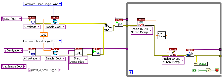
The following block diagram shows a typical deterministic control loop application. First, an analog value is read. This value corresponds to the process variable. This value is compared to the set point, which is specified in the Ctrl Algrthm VI in the diagram, and adjusted as necessary within the while loop, possibly using a PID algorithm. The adjusted value is then written. This value corresponds to the actuator output.
In the block diagram, the sampling rates are the same for analog input and output. Because the example shown assumes a single DAQ device, the Start Trigger synchronizes the analog input and analog output tasks. For multiple devices, synchronization works differently. Refer to Synchronization for more information. Notice also that the slave taskthe analog output taskstarts before the analog input task. Finally, within the loop, the Wait for Next Sample Clock VI checks to make sure that the loop executes within the specified sampling rate. If it does not, this VI returns an error.

See Also