OUTPut:ALARm:SLOPe
OUTPut:ALARm:SLOPe
Syntax
OUTPut:ALARm:SLOPe <edge>
OUTPut:ALARm:SLOPe?
Description
This command selects the slope of the pulse from the four TTL alarm outputs (the selected configuration applies to all four alarm output lines). The four alarm outputs are available from the rear-panel Alarm Output connector.
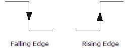
If you select the negative/falling edge, 0 V (TTL low) indicates an alarm. If you select the positive/rising edge, +5V (TTL high) indicates an alarm.

Changing the slope of the output lines may cause the lines to change state.
Used With:
- 34901A 20 Channel Multiplexer (2/4-wire) Module
- 34902A 16 Channel Multiplexer (2/4-wire) Module
- 34907A Multifunction Module (digital input and totalizer)
- 34908A 40 Channel Single-Ended Multiplexer Module
Parameters
Name Type Range of Values Default Value <edge> Discrete {NEGative|POSitive} This is a required parameter.
The keyword NEGative refers to a falling edge, and the keyword POSitive refers to a rising edge, as shown below.
Remarks
- A Factory Reset (*RST command) resets the slope to the negative/falling edge.
Return Format
The query returns NEG or POS. The selected configuration applies to all four alarm output lines.
Examples
The following command selects the positive/rising edge on all four alarm output lines.
OUTP:ALAR:SLOP POS
The following query returns the slope of the four alarm output lines.
OUTP:ALAR:SLOPE?
Typical Response: POS
See Also