|
ADC_MEASUREMENT
|
Usage
This example demonstrates the conversion of the required ADC channel. If the converted channel is above a threshold voltage then a pin is set to Low else it would be set to High. The port pin is connected to a on-board LED. This would switch on/off the LED depending on the potentiometer value(Potentiometer controls the input voltage for the ADC).
Instantiate the required APPs
Drag an instance of ADC_MEASUREMENT APP and DIGITAL_IO APP. Update the fields in the GUI of these APPs with the following configuration.
Configure the APPs
ADC_MEASUREMENT APP:
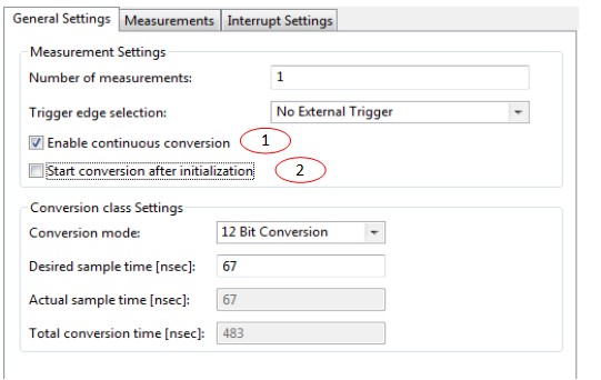
-
Enable continuous conversion.
- Disable Start conversion after initialization.
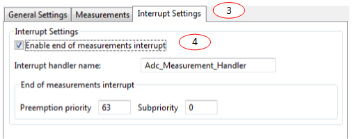
- Goto Interrupt settings Tab.
-
For XMC1100:
Enable interrupt after each measurement.
For other devices:
Enable end of measurements interrupt.
DIGITAL_IO APP:
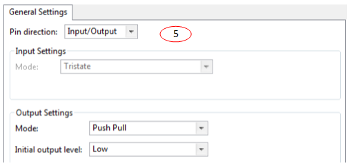
- Set pin direction to output by choosing - Pin direction : Input/Output
Manual pin allocation
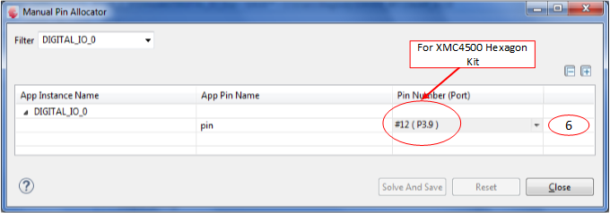
-
Select the pin to be toggled (on-board LED)
Note:The pin number is specific to the development board chosen to run this example. The pin shown in the image above may not be available on every XMC boot kit. Ensure that a proper pin is selected according to the board.
-
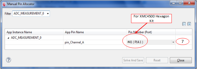
Select the potentiometer Pin present in the boot kit
Note:The pin number is specific to the development board chosen to run this example. The pin shown in the image above may not be available on every XMC boot kit. Ensure that a proper pin is selected according to the board.
Generate code
Files are generated here: '<project_name>/Dave/Generated/' ('project_name' is the name chosen by the user during project creation). APP instance definitions and APIs are generated only after code generation.
-
Note: Code must be explicitly generated for every change in the GUI configuration.
Important: Any manual modification to the APP specific generated files will be overwritten by a subsequent code generation operation.�
Sample Application (main.c)
 #include <DAVE.h>           //Declarations from DAVE Code Generation (includes SFR declaration)

 XMC_VADC_RESULT_SIZE_t result;
 void Adc_Measurement_Handler()
 {
 #if(UC_SERIES != XMC11)
     result = ADC_MEASUREMENT_GetResult(&ADC_MEASUREMENT_Channel_A);
 #else
     result = ADC_MEASUREMENT_GetGlobalResult();
 #endif

     if(result >= 2048)
     {
         DIGITAL_IO_SetOutputLow(&DIGITAL_IO_0);
     }
     else
     {
         DIGITAL_IO_SetOutputHigh(&DIGITAL_IO_0);
     }
 }


 int main(void)
 {
   DAVE_STATUS_t status;

   status = DAVE_Init();     /* Initialization of DAVE Apps  */

   if(status == DAVE_STATUS_FAILURE)
   {
     /* Placeholder for error handler code. The while loop below can be replaced with an user error handler */
     XMC_DEBUG(("DAVE Apps initialization failed with status %d\n", status));
     while(1U)
     {
     }
   }

   ADC_MEASUREMENT_StartConversion(&ADC_MEASUREMENT_0);

   while(1U);

   return 1;
 }
Build and Run the Project
Observation
Change the potentiometer value connected to the board. If the converted value is greater than 2048(Vcc/2) the LED will be turned on else it would remain switched off.
Calibration work around for XMC1100/XMC1200/XMC1300 AA step devices
NOTE: invoke the API VADC_complete_calibration() to do both startup calibration and gain calibration.
 #define SHS0_CALOC0 ((uint32_t *)0x480340E0)
 #define SHS0_CALOC1 ((uint32_t *)0x480340E4)
 #define SHS0_CALCTR ((uint32_t *)0x480340BC)

 #define SHS_CALLOC0_CLEAR_OFFSET (0x8000)
 #define REG_RESET (0x00)
 #define GLOBCFG_CLEAR (0x80030000)
 #define CLEAR_OFFSET_CALIB_VALUES         *SHS0_CALOC0 = SHS_CALLOC0_CLEAR_OFFSET;\
                                         *SHS0_CALOC1 = SHS_CALLOC0_CLEAR_OFFSET

 void adc_gain_calib(void)
 {
   uint16_t i = 18000;
   uint32_t adc_result_aux;

   /* ADC_AI.004 errata*/
   *SHS0_CALCTR = 0X3F100400;

   /* add a channel in group-0 for dummy conversion*/
   VADC->BRSSEL[0] = VADC_BRSSEL_CHSELG0_Msk;

   /*Clear the DPCAL0, DPCAL1 and SUCAL bits*/
   VADC->GLOBCFG &= ~( VADC_GLOBCFG_DPCAL0_Msk | VADC_GLOBCFG_DPCAL1_Msk | VADC_GLOBCFG_SUCAL_Msk);

   /* Clear offset calibration values*/
   CLEAR_OFFSET_CALIB_VALUES;

   VADC->BRSMR = (1 << VADC_BRSMR_ENGT_Pos);
 #if UC_SERIES != XMC11
   VADC_G0->ARBPR = (VADC_G_ARBPR_ASEN2_Msk);
 #endif
   /*Trigger dummy conversion for 9* 2000 times*/

   while(i > 0)
   {
       /*load event */
       VADC->BRSMR |= VADC_BRSMR_LDEV_Msk;
 #if UC_SERIES != XMC11
       /*Wait until a new result is available*/
       while(VADC_G0->VFR == 0);

       /*dummy read of result */
       adc_result_aux = VADC_G0->RES[0];
 #else
       /*Wait untill a new result is available*/
       while((VADC->GLOBRES & VADC_GLOBRES_VF_Msk) == 0);

       /*dummy read of result */
       adc_result_aux = VADC->GLOBRES;
 #endif

       /* Clear offset calibration values*/
       CLEAR_OFFSET_CALIB_VALUES;
       i--;
   }

   /* to avoid a warning*/
   adc_result_aux &= adc_result_aux;

   /* Wait until last gain calibration step is finished */
   while ( (SHS0->SHSCFG & SHS_SHSCFG_STATE_Msk) != 0 )
   {
       /* Clear offset calibration values*/
       CLEAR_OFFSET_CALIB_VALUES;
   }
   /* Re enable SUCAL DPCAL */
   VADC->GLOBCFG |= ( VADC_GLOBCFG_DPCAL0_Msk | VADC_GLOBCFG_DPCAL1_Msk);
   VADC->BRSMR     = 0x00;
   VADC->BRSSEL[0] = 0x00;
 #if UC_SERIES != XMC11
   VADC_G0->REFCLR = 1U;
   VADC_G0->ARBPR &= ~(VADC_G_ARBPR_ASEN2_Msk);
 #endif
 }

 void VADC_complete_calibration(void)
 {
   uint32_t wait;
   *SHS0_CALOC0 = REG_RESET;
   *SHS0_CALOC1 = REG_RESET;

   //enable the StartUp calibration in the VADC
   VADC->GLOBCFG |= (1 << VADC_GLOBCFG_SUCAL_Pos & VADC_GLOBCFG_SUCAL_Msk)|
                    (1 << VADC_GLOBCFG_DPCAL0_Pos & VADC_GLOBCFG_DPCAL0_Msk);

   // Wait for 1920cycles or 60us for the startup calibration to complete
   wait = 20;

   while(wait > 0)
   {
       wait--;
       // Clear offset calibration values
       CLEAR_OFFSET_CALIB_VALUES;
   }
   adc_gain_calib();
 }