|
ADC_MEASUREMENT
|
Overview
The APP measures the connected multiple input signals. It uses the "background request source" of Versatile Analog to Digital Converter (VADC) peripheral to provide the following functionalities.
- Measures a linear sequence of analog inputs.
- Provides software and hardware controlled start of measurements.
-
Provides the following interrupt notifications
- Notification at the end of all measurements (Not applicable for XMC1000).
- Notification after each individual measurement completion.
Details of provided functionalities
-
ADC Measurement Sequence:
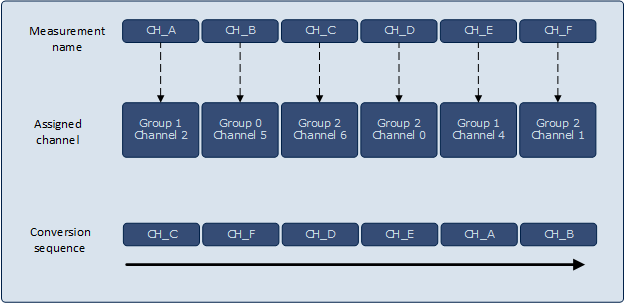
The measurement names configured in the APP GUI "Measurement Table" are assigned to individual channels under background scan request source of VADC peripheral. The assigned channels can be from any groups defined in the VADC hardware. The assigned channels depend on the analog pin selected. All these assigned channels get converted in a fixed linear sequence starting from highest group channel to lowest group channel (G3_CH7 to G0_CH0). This is explained with an example as follows:
If 6 measurements are configured in the GUI named as CH_A, CH_B, CH_C, CH_D, CH_E, CH_F. The channels assigned to the measurements is as follows
CH_A = GROUP-1 CHANNEL-2
CH_B = GROUP-0 CHANNEL-5
CH_C = GROUP-2 CHANNEL-6
CH_D = GROUP-2 CHANNEL-0
CH_E = GROUP-1 CHANNEL-4
CH_F = GROUP-2 CHANNEL-1
The order of conversion sequence for these measurements is as shown in the following figure

Figure 1 : Conversion Sequence -
ADC Measurement start mode:
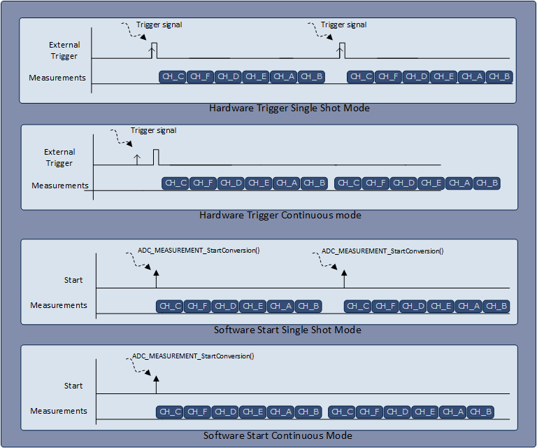
To start the ADC measurements, the APP provides the following four different modes.- Hardware Trigger Single Shot Mode
- Hardware Trigger Continuous mode
- Software Start Single Shot Mode
- Software Start Continuous Mode
Software Start mode need ADC_MEASUREMENT_StartConversion() API to start the conversions of assigned channels. The software start can also be triggered in the APP initialization by setting the " Start conversion after initialization" parameter in the General Settings TAB.
Hardware Start mode needs external trigger signal to start the conversions of the assigned channels. This mode can be enabled by setting "Trigger Edge Selection" field in the General Settings TAB to any one edge (Rising/ Falling / Both edges). The trigger signal can be applied from other APPS such as PWM / EVENT_GENERATOR.
Both software and hardware start modes can configure the ADC to measure the inputs repeatedly by enabling the "Enable continuous conversion" option in the GUI. If single shot mode is selected, subsequent conversion (sequence) must be triggered again.
The details of four start modes are explained in the following figure

Figure 2 : ADC Measurement start mode -
Interrupt Notifications:
-
XMC1100 Series
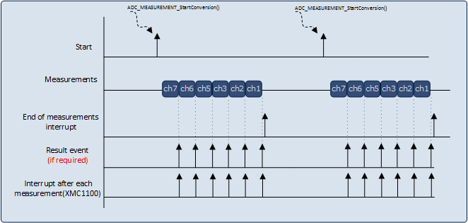
If enabled, the interrupt is generated after each measurement is completed(one channel conversion). To enable the interrupt notification, select GUI field "Enable interrupt after each measurement" under "Interrupt Settings" TAB. It is mandatory to read the converted results in the interrupt notification function callback to allow the next conversions to happen. All the measurement channels share a common GLOBAL result register in "wait for read mode" of operation. -
Other XMC Series
If enabled, an interrupt is raised after all the measurements are completed once(all channels are converted once). To enable the interrupt notification, select GUI field "Enable end of measurement interrupt" under "Interrupt Settings" TAB. Additionally on each measurement completion (one result available) an result event notification can be triggered by enabling the "Result event" field associated with the particular measurement name.
The detailed analysis of the interrupt notifications is explained in the following figure.

Figure 3 : Interrupt Notifications -
APP Structure
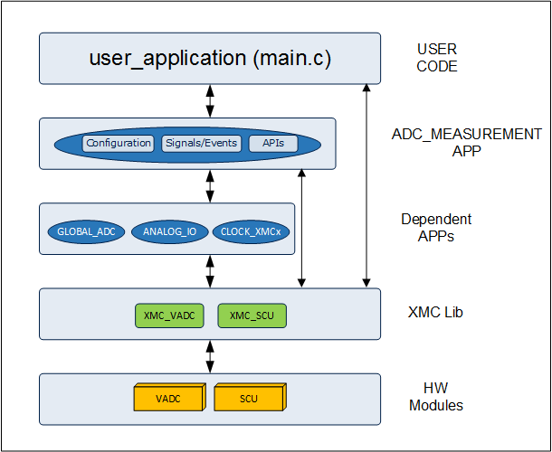
Figure 4 , shows how the APP is structured in DAVE. XMC controllers provides the VADC module for analog to digital conversion. The XMC Lib layer provides abstraction for these hardware modules. The ADC_MEASUREMENT APP uses VADC and SCU LLDs and other dependent APPS such as GLOBAL_ADC ,ANALOG_IO and CLOCK_XMCx for the functional execution.

Limitations:
- The available channels depends on the device that is selected and it might not be possible to achieve the maximum value shown for the "Number of measurements" in the UI of the APP.
Supported Devices
The APP supports below devices:
- XMC4800 / XMC4700 Series
- XMC4500 Series
- XMC4400 Series
- XMC4300 Series
- XMC4200 / XMC4100 Series
- XMC1400 Series
- XMC1300 Series
- XMC1200 Series
- XMC1100 Series
Reference
- XMC4800 / XMC4700 Reference Manual
- XMC4500 Reference Manual
- XMC4400 Reference Manual
- XMC4300 Reference Manual
- XMC4200 / XMC4100 Reference Manual
- XMC1400 Reference Manual
- XMC1300 Reference Manual
- XMC1200 Reference Manual
- XMC1100 Reference Manual