 |
If you are one of those developers who want to create tree descendants, which perhaps involve visual changes in Virtual Treeview then you need to know how the control paints itself (as outlined in Paint cycles and stages). What happens with the resulting image and how it can be used for certain tasks like printing? Some answers are in this topic.
Some methods in Virtual Treeview work with an internal tree image, e.g. painting or hit determination. This tree image does not really exist but is rather an imagination of the entire tree drawn to an infinitely sized sheet. In this picture the tree is always drawn at position (0, 0) and advances to positive horizontal and vertical values which reach out to the right and down, respectively. This also means that coordinates given in this fictional image are always positive.
A display function like the WM_PAINT handler can now take a rectangle of this full image (in PaintTree this is called the window) and let it draw to any location in a target canvas. This allows to draw a part of the entire image even if the tree window is scrolled or needs otherwise to be moved (e.g. when dragging or printing). In order to get the full dimension of the tree image call GetTreeRect, which returns a rectangle always starting at (0, 0) and extending at least to client area size but usually much further (determined by the private variables FRangeX and FRangeY which also determine the scroll bar values).
In order to maintain the visual portion of the tree image two offset values are maintained which specify the horizontal and vertical distance relative to the client area of the tree control. These offsets (OffsetX, OffsetY and OffsetXY) are therefore negative. This means 0 means no offset at all and -100 means the tree is scrolled by 100 pixels. Values > 0 are always made to 0.
How does this now fit together when you want, say, to print a part of the tree to a memory or printer canvas? Have a look at the image below:
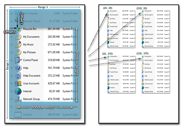
On the left pane you can see a typical tree view of which only a specific part is visible. This situation is visualized by the non-shaded rectangular region. The right pane shows the reproduction of the visible part to different locations. The entire tree image size corresponds to the internal FRangeX and FRangeY variables of the tree view. When drawing a part of the window the method PaintTree needs to know the size and position of the part to draw. This is given by a TRect structure passed in the Window parameter. For normal screen display this rectangle structure consists of the current scroll offsets (properties OffsetX and OffsetY or OffsetXY for both together given as TPoint) and the size of the client area of the tree control. This rectangle is usually also intersected with the current clipping region to avoid painting parts of the tree which are not invalid.
The place where the image is to be painted is given in the parameter Target. This point specifies the physical location in the target canvas where to draw the content of the region specified by Window. Note that these coordinates are usually (but wrongly) considered as being physical pixels. This might be true for screen or bitmap output but is not for the printer where a single pixel would be much too small. Hence another term is used here: logical coordinates. The actual size of one unit of these coordinates can either be a single pixel but also a millimeter, inch or even some other odd size. The interpretation is determined by the mapping mode of the target canvas (device context, DC) and its window and viewport extents. For more information about mapping modes see the online help or MSDN under SetMapMode and for DC extents under SetWindowExtEx as well as SetViewportExtEx. With the help of mapping modes and window/viewport extents you can greatly customize the outcome of PaintTree. These APIs are usually also used to provide a print preview.
|
What do you think about this topic? Send feedback!
|