Vector Length and Direction Code (Concept)
From AutoCAD
|
|
|
|
|
|
|
A simple shape specification byte contains vector length and direction encoded into one specification byte.
A simple shape specification byte contains vector length and direction encoded into one specification byte (one specbyte field). Each vector length and direction code is a string of three characters. The first character must be a 0, which indicates to AutoCAD that the next two characters are interpreted as hexadecimal values. The second character specifies the length of the vector in units. Valid hexadecimal values range from 1 (one unit long) through F (15 units long). The third character specifies the direction of the vector. The following figure illustrates the direction codes.

All the vectors in the preceding figure were drawn with the same length specification. Diagonal vectors stretch to match the X or Y displacement of the closest orthogonal vector. This is similar to the action of the snap grid in AutoCAD.
The following example constructs a shape named DBOX with an arbitrarily assigned shape number of 230.
*230,6,DBOX
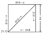
014,010,01C,018,012,0
The preceding sequence of specification bytes defines a box one unit high byone unit wide, with a diagonal line running from the lower left to the upper right. After saving the file as dbox.shp, use the COMPILE command to generate the dbox.shx file. Use the LOAD command to load the shape file containing this definition, and then use the SHAPE command as follows:
Command: shape
Enter shape name or [?]: dbox
Specify insertion point: 1,1
Specify height <current>: 2
Specify rotation angle <current>: 0
The resulting shape is shown in the following illustration.