


|
|

|

|
|

|
Special codes 00C and 00D (12 and 13) provide another mechanism for including arc segments in shape descriptions. They are similar to codes 8 and 9 in that you can use them to specify X-Y displacements. However, codes 00C and 00D draw arcs by applying a bulge factor to the displacement vector. Code 00C draws one arc segment, while code 00D draws multiple arc segments (polyarcs) until it is terminated by a (0,0) displacement.
Code 00C must be followed by three bytes describing the arc:
0C,X-displacement,Y-displacement,Bulge
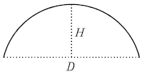
Both the X and Y displacement and the bulge, which specifies the curvature of the arc, can range from -127 to +127. If the line segment specified by the displacement has length D, and the perpendicular distance from the midpoint of that segment has height H, the magnitude of the bulge is ((2* H / D) * 127). The sign is negative if the arc from the current location to the new location is clockwise.
A semicircle has bulge 127 (or -127) and is the greatest arc that can be represented as a single-arc segment using these codes (use two consecutive arc segments for larger arcs). A bulge specification of 0 is valid and represents a straight-line segment. Note, however, that using code 8 for a straight-line segment saves a byte in the shape description.
The polyarc code (00D, or 13) is followed by 0 or by more arc segment triples, and is terminated by a (0,0) displacement. Note that no bulge is specified after the final displacement. For example, the letter S might be defined by the following sequence:
13,(0,5,127),(0,5,-127),(0,0)
Zero bulge segments are useful within polyarcs to represent straight segments; they are more efficient than terminating the polyarc, inserting one straight segment, and then starting another polyarc.
The number -128 cannot be used in arc segment and polyarc definitions.